Lightweight wear-resistant weld overlay

a technology of weld overlay and light weight, which is applied in the field of lightweight wear-resistant weld overlay, can solve the problems of affecting the life of the screen is relatively short, and the hardfacing system, involving wc, has problems associated with it, so as to increase the overall weight of the metal substrate and increase the wear resistance

Inactive Publication Date: 2006-08-24
CANADIAN OIL SANDS +6
View PDF21 Cites 30 Cited by
  • Summary
  • Abstract
  • Description
  • Claims
  • Application Information

AI Technical Summary

Benefits of technology

[0018] The metal substrate produced by the hardfacing process herein exhibits increased...

Problems solved by technology

Both the dry, as—mined oil sand and the slurry obtained by mixing the oil sand with heated water are particularly abrasive and erosive.
Thus, the life of such a screen was relatively short, in the order of 500,000 tons of slurry treated.
The current hardfacing system, involving WC, has problems associated with it.
This is undesirable as one wants to ma...

Method used


Image

  • Lightweight wear-resistant weld overlay
  • Lightweight wear-resistant weld overlay
  • Lightweight wear-resistant weld overlay

Examples


example i

DISCUSSION RELATIVE TO EXAMPLE I

[0054] A reasonably wide range of welding parameters produced results similar to the foregoing. This is in contrast to the very tight controls on welding parameters one requires when PTA welding WC—Ni—Cr—B—Si overlays to produce acceptable carbide distribution throughout the weld. The welding parameters are controlled by WC decomposition and poor distribution (due to slower cooling rates) at higher welding heat inputs and lack of fusion at low heat inputs.

[0055] The poor distribution of WC in Ni—Cr—B—Si metal matrix material is partially due to the significantly different densities of WC and WC / W2C (15.8-17.2 g / cm3) compared to approximately 8.9 g / cm3 for nickel alloys. In contrast, B4C or SiC with densities of 2.52 and 3.21 g / cm3, respectively, are much more compatible with aluminum which has a density of 2.7 g / cm3. Practically, this means that a much larger welding parameter window is possible with the present system, which allows the welder more f...

example ii

[0058] This Example demonstrates that SiC can be substituted for some or all of the B4C.

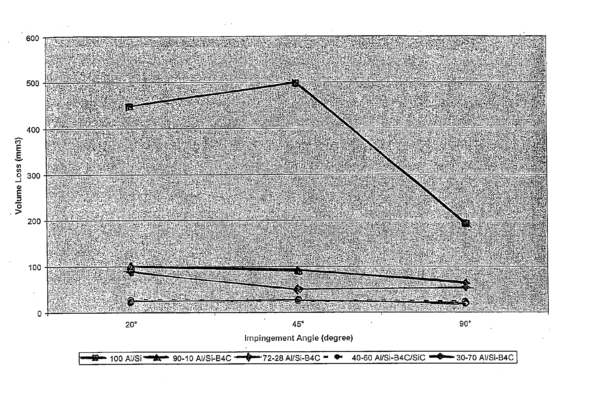
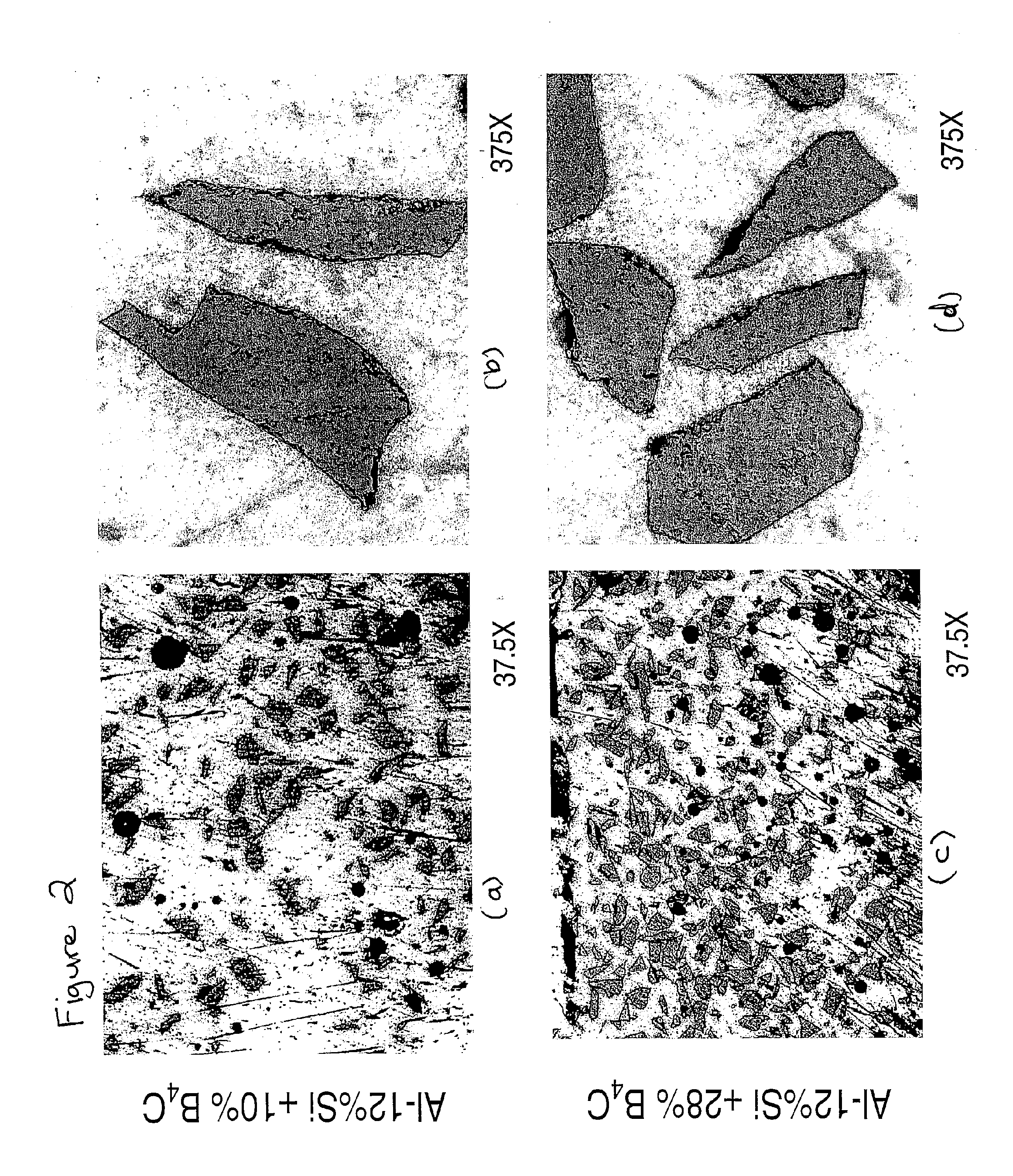
[0059] The same welding parameters, equipment and procedures were used to produce weld overlays using a 40 wt. % Al-12 wt. % Si+30 wt. % B4C+30 wt. % SiC feed mixture as in Example I. FIG. 10 shows that this combination gave essentially the same erosion testing results as the 30 wt. % Al-12 wt. % Si+70 wt. % B4C combination. Additionally, the photomicrograph in FIG. 11 shows that the dark phase (SiC) and the light phase (B4C) carbides are very angular indicating little decomposition of the carbides during processing.

[0060] This substitution would be done in consideration of the properties required for the final weld overlay. It appears from FIG. 10 that erosion performance is acceptable for both the B4C and B4C / SiC mixture tested. However, the high silicon content of the aluminum alloy also inhibits the degradation of SiC, which begins decomposing at 1700° C. B4C does not decompose but sublimes...

example iii

[0061] The aluminum-carbide metal matrix composite overlays of the invention can be joined to most other metals either directly (as shown in Examples I and II) or indirectly by precoating the other metals or using a bi-metallic transition piece. For example, to hardface a carbon steel substrate, the overlay is deposited onto an intermediate alloy, which is placed onto the carbon steel substrate by a number of methods known to a person skilled in the art. This is often referred to in the art as “buttering” the steel with a “butter layer” such as a nickel or copper alloy.

[0062] Methods for buttering steel can be found in American Welding Society Welding Handbook, Materials and Applications—Part 1, “Aluminum and Aluminum Alloys, Joining to Other Metals”, (American Welding Society 1996), p. 97, and include the following:

[0063] 1. brazing a nickel or copper based alloy onto the carbon steel surface;

[0064] 2. roll bonding, cladding or explosion bonding a nickel or copper based alloy of...


PUM

PropertyMeasurementUnit
Sizeaaaaaaaaaa
Sizeaaaaaaaaaa
Sizeaaaaaaaaaa

Abstract

A powder form of a hard phase component, selected from the group consisting of boron carbide, silicon carbide and a mixture of boron carbide and silicon carbide, is combined with an aluminum alloy matrix powder and applied to a metal substrate using plasma transferred arc (“PTA”) welding to produce a hardfaced structure having a wear-resisting carbide metal matrix composite overlay. The metal substrate can be any metal structure, such as an aluminum, aluminum alloy, steel or carbon steel structure, where wear resistance is desirable. Further, a process for hardfacing a metal substrate is disclosed comprising feeding a hard phase powder, selected from the group consisting of boron carbide, silicon carbide and a mixture of boron carbide and silicon carbide, and an aluminum alloy metal matrix powder to an operative PTA welding torch and welding to form a carbide metal matrix composite overlay fused to a metal substrate. The metal substrate produced by the hardfacing process herein exhibits increased wear resistance without a significant increase in the overall weight of the metal substrate.

Description

[0001] The present invention relates generally to a wear-resistant weld overlay applied to a substrate and to a process for producing the resulting hardfaced structure. More specifically, the present invention relates to a carbide metal matrix composite weld overlay which offers high wear resistance with reduced weight. BACKGROUND OF THE INVENTION [0002] The invention has been developed in connection with hardfacing of metal components used in mining and processing of oil sand and it will be described herein in connection with that environment. However, it is contemplated that the invention may find application in other fields of use as well. [0003] Oil sand is mined, trucked, slurried, conveyed in a pipeline and processed, using various equipment and vessels, all with the objective of recovering contained bitumen (a form of heavy viscous oil). Both the dry, as—mined oil sand and the slurry obtained by mixing the oil sand with heated water are particularly abrasive and erosive. [000...

Claims


Application Information

Patent Timeline
IPC IPC(8): C22C21/00B23K10/02
CPCB23K9/04B23K10/027Y10T428/12493Y10T428/12972Y10T428/12736Y10T428/12764
Inventor CHIOVELLI, STEFANO
Owner CANADIAN OIL SANDS
Why Eureka
Try Eureka