Position-tracing system

a position-tracing and object technology, applied in the field of system and method for tracking the position of objects, can solve the problems of unreliable location tracking indoors or in other environments, system limitations, and ineffectiveness of gps systems, and achieve the effects of enhancing accuracy, enhancing accuracy, and reducing costs

Active Publication Date: 2006-08-24
PINC SOLUTIONS
View PDF54 Cites 56 Cited by
  • Summary
  • Abstract
  • Description
  • Claims
  • Application Information

AI Technical Summary

Benefits of technology

[0008] When the object enters an area (such as a facility, warehouse, campus, etc.) where greater position resolution is required (a so-called “high resolution area”), the position tracking system may transition to a corresponding high-resolution mode. The mode transition may be activated, for example, by a wireless activation signal provided at the ingress of the high-resolution area. The greater position resolution may be realized using other wireless signals, from a wireless aiding system within the high-resolution environment, combined with the inputs from the inertial sensors. The tracking system (e.g., at either the tracking device, the host processing system, or distributed between these components) may compute the amount of displacement in the longitudinal, latitudinal and altitudinal directions based on the measurements from the inertial sensors. When aided by the wireless reference position signals from the wireless aiding system, the combined implementati...

Problems solved by technology

However, such systems typically suffer from limitations caused by line-of-sight requirements for location signals and/or interference caused by the environment in which they operate (e.g., multi-path fading or radio waves in an indoor setting).
In addition, although much effort has gone into extending the operating range for Global Positioning System (GPS) and GPS-like technologies with more and more sophisticated sof...

Method used


Image

  • Position-tracing system
  • Position-tracing system
  • Position-tracing system

Examples


Embodiment Construction

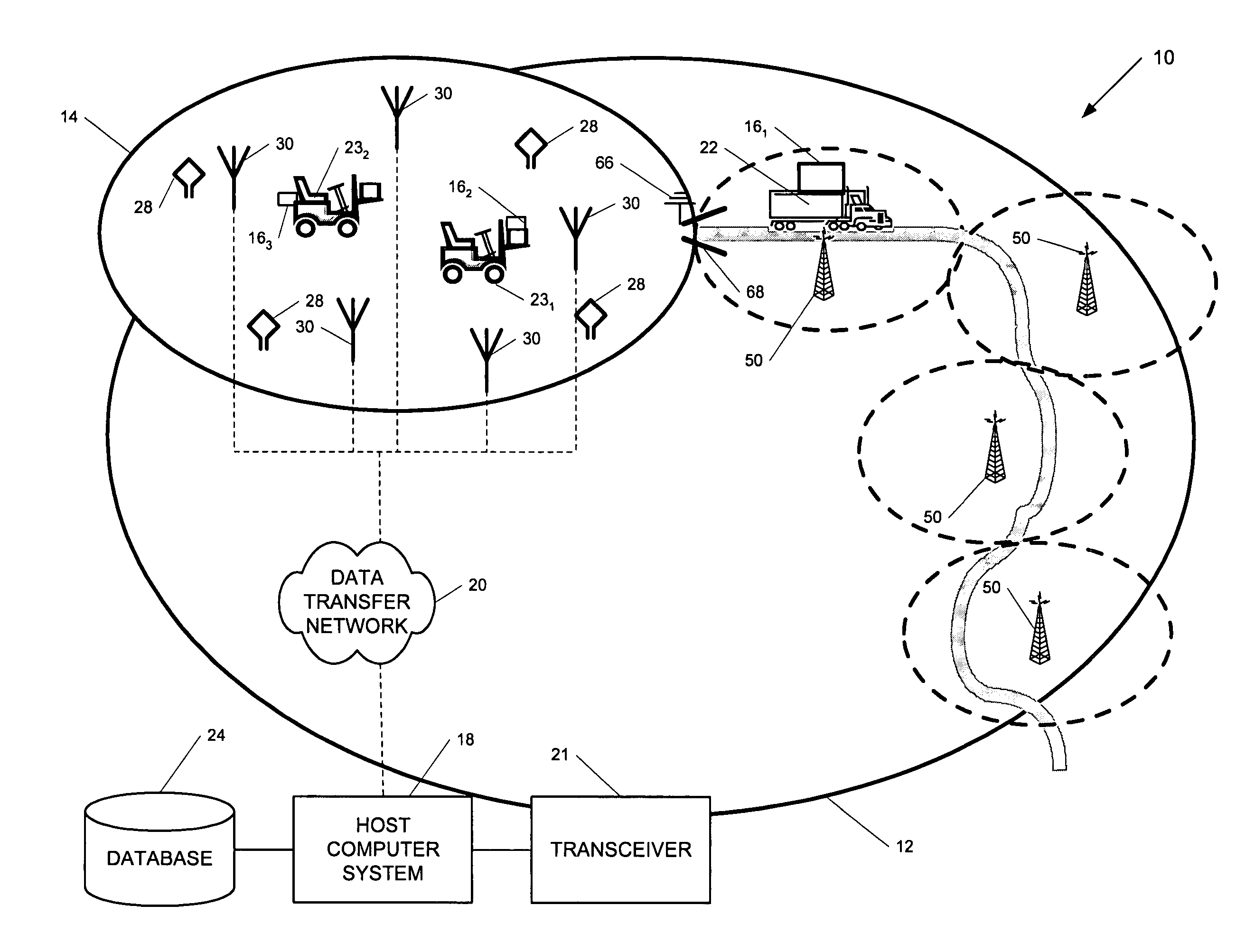
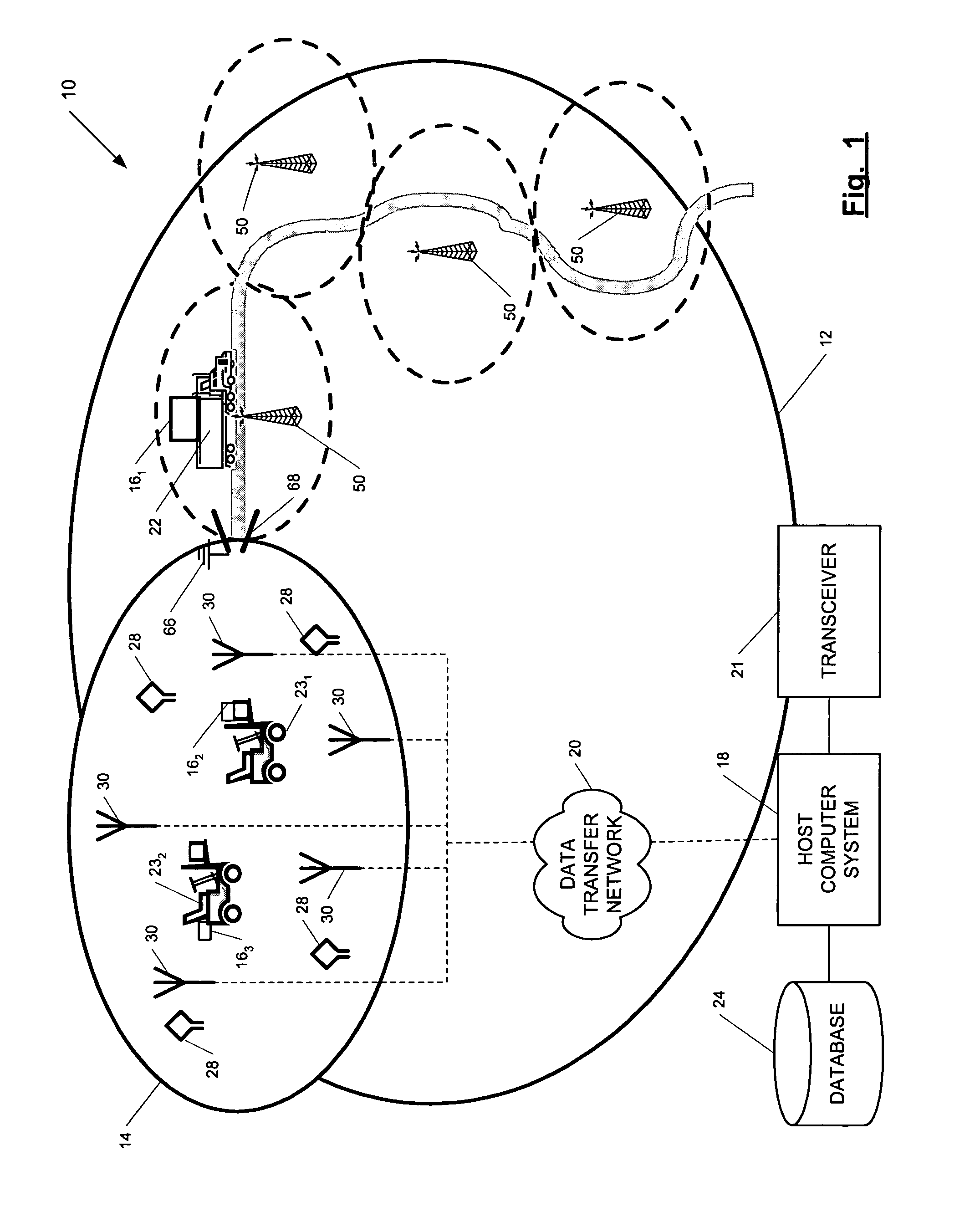
[0020]FIG. 1 is a diagram of a position-tracking system 10 according to various embodiments of the present invention for tracking the position of one or more mobile objects in real-time (i.e., within a small response time) as the objects travel about. The tracked objects may be any tangible object that is capable of moving, whether by its own mobility system or because it is capable of being transported by other means, such as conveyor belts, vehicles, lifts, persons, etc. Accordingly, the tracked objects may be goods, containers or supports for goods, vehicles or equipment for moving goods, etc. Also, the tracked objects or goods may or may not have RFID tags. That is, the position tracking system described herein may be used in conjunction with RFID technology or in lieu of it.

[0021] The tracking system 10 tracks the position of the objects as they travel through areas, such as area 12, where very high position location resolution is not needed, and areas, such as area 14, where ...


PUM


Abstract

A position-tracking system for tracking the position of an object is disclosed. According to various embodiments, the tracking system includes a tracking device that is connected to or otherwise affixed to the object to be tracked. The tracking device may include, among other things, an inertial sensor assembly, radio transceivers and a processor. The position tracking system may also include a host processing system that is in communication with the tracking device. The position tracking system may provide variable-resolution position information based on the environment in which the object is moving. In a “wide resolution” area, the system may compute a general position for the object based on a wireless telephone network Cell-ID/map correlation architecture. In a high-resolution area, greater position resolution may be realized from the combination of a wireless aiding system and inputs from the inertial sensors. In the high-resolution mode, the system may exploit distinct patterns of motion that can be identified as motion “signatures” that are characteristic of certain types of motion. Kinematic (or object movement) models may be constructed based on these motion signatures and the position tracking system may estimate the state of the object based on the kinematic model for the current mode of the object. Adaptive and cascaded Kalman filtering may be employed in the analysis to more accurately estimate the position and velocity of the object based on the motion pattern identified.

Description

CROSS-REFERENCE TO RELATED APPLICATIONS [0001] The present application is being contemporaneously filed with a commonly-owned application by the same inventors entitled “Position-Tracking Device for Position-Tracking System,” Attorney docket number 050037. BACKGROUND OF THE INVENTION [0002] The present invention is generally directed to systems and methods for tracking the position of objects. [0003] Position-tracking systems seek to identify the location of mobile objects in real-time and are used in a wide variety of applications, including transportation, logistics management, healthcare, security, etc. Position-tracking systems that can provide continuous location information are desirable for applications that require non-interrupted visibility of the mobile object through a journey. For objects that are moved with a vehicle (such as inter-modal shipping containers or trailers), being able to locate the position of the objects in real-time can help improve the efficiency of sup...

Claims


Application Information

Patent Timeline
IPC IPC(8): G08B1/08H04Q7/20G01C21/28G08G1/123
CPCG01C21/165G06Q10/08G08G1/20
Inventor KIANG, MENG-HSIUNGGOLLU, ALEKS
Owner PINC SOLUTIONS
Why Eureka
Try Eureka