Oxidation resistant electrode for fuel cell

Inactive Publication Date: 2006-08-24
GM GLOBAL TECH OPERATIONS LLC
View PDF13 Cites 37 Cited by
  • Summary
  • Abstract
  • Description
  • Claims
  • Application Information

AI Technical Summary

Benefits of technology

[0012] Thus, this invention advantageously provides a potential method to reduce the carbon corrosion rate under fuel cell operating conditions while desirable intrinsic properties of carbon

Problems solved by technology

However, in the presence of an acidic environment, oxygen at the cathode, and an electric field during PEM operation, maintaining the overall stability of such a supported catalyst remains a challenge in commerc

Method used


Image

  • Oxidation resistant electrode for fuel cell
  • Oxidation resistant electrode for fuel cell
  • Oxidation resistant electrode for fuel cell

Examples


Example

[0020] Many United States patents assigned to the assignee of this invention describe electrochemical fuel cell assemblies having an assembly of a solid polymer electrolyte membrane and electrode assembly. For example, FIGS. 1-4 of U.S. Pat. No.6,277,513 include such a description, and the specification and drawings of that patent are incorporated into this specification by reference.

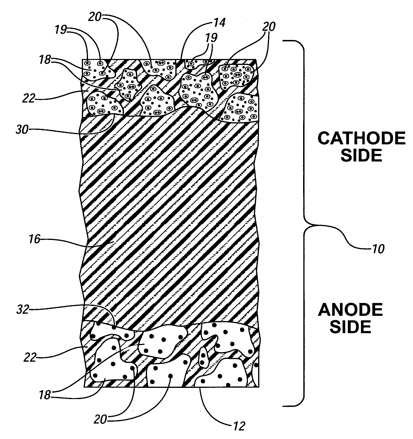
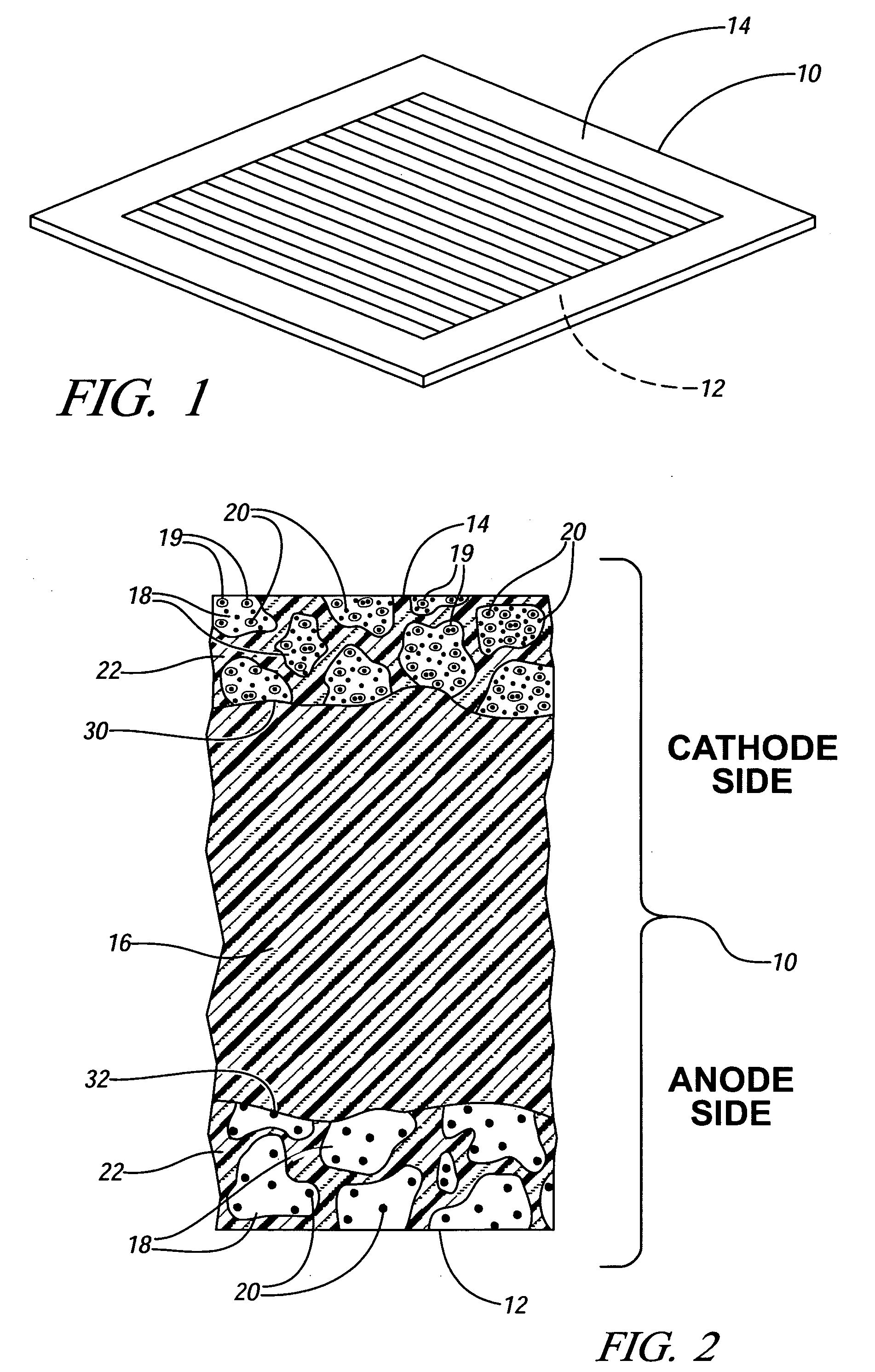
[0021]FIG. 1 of this application illustrates a membrane electrode assembly 10 which is a part of the electrochemical cell illustrated in FIG. 1 of the '513 patent. Referring to FIG. 1 of this specification, membrane electrode assembly 10 includes anode 12 and cathode 14. In a hydrogen / oxygen (air) fuel cell, for example, hydrogen is oxidized to H+ (protons) at the anode 12 and oxygen is reduced to water at the cathode 14.

[0022]FIG. 2 provides an enlarged, fragmentary, cross-sectional schematic view of a membrane electrode assembly 10 similar to that shown in FIG. 1. In FIG. 2, anode 12 and cathode 14 ...


PUM


Abstract

An oxygen reducing electrode for a fuel cell comprises carbon particles as support for catalyst particles. The carbon particles are coated with smaller particles of a metal oxide and/or metal phosphate (for example, TiO2 particles) to impede destructive oxidation (corrosion) of the carbon particles while permitting suitable electrical conductivity between the carbon particles. The catalyst is carried on the smaller particle-coated carbon particles. Titanium dioxide particles can be dispersed on carbon particles suspended in a liquid medium by ultrasonic decomposition of a suitable titanium precursor compound.

Description

CROSS-REFERENCE TO RELATED APPLICATION [0001] This application claims the benefit of U.S. Provisional Application 60 / 654307, filed Feb. 18, 2005 and titled “Method for Preventing Oxidation of a Carbon Surface and Structure Thereof.” The disclosure of that provisional application is incorporated herein by reference.TECHNICAL FIELD [0002] This invention relates to a method for mitigating oxidation of a carbon surface with a particulate metal oxide oxidation barrier, especially when the carbon supports a catalyst in an oxidizing environment. In a more specific embodiment, this invention relates to coating carbon particles (intended as a support for catalyst particles) with smaller particles of a metal oxide, such as titanium dioxide, to inhibit oxidation of the carbon while retaining suitable electrical conductivity between carbon particles. Thus, when catalyst particles are applied to the carbon / metal oxide particle combination the resulting supported catalyst is resistant to destruct...

Claims


Application Information

Patent Timeline
IPC IPC(8): H01M4/96H01M8/10H01M4/88
CPCH01M4/8652H01M4/8657H01M4/9016H01M4/9083H01M4/92H01M4/926H01M8/1002H01M8/1004H01M2004/8689Y02E60/521H01M8/1007Y02E60/50H01M4/88H01M4/96H01M8/10
Inventor MANCE, ANDREW M.CAI, MEICARRIQUIRY, CECILIARUTHKOSKY, MARTIN S.
Owner GM GLOBAL TECH OPERATIONS LLC
Why Eureka
Try Eureka