
Electrolytic copper foil with low roughness surface and process for producing the same

a technology of copper foil and low roughness, which is applied in the direction of printed circuit manufacturing, printed circuit aspects, and the improvement of the adhesion of the metal to the substrate, etc., can solve the problems of low roughness of the foil moderate uneven surge on the roughness surface, and difficult to reduce the difference in roughness between gloss surface and roughness surface. , to achieve the effect of low roughness surfa

Inactive Publication Date: 2006-08-31
FUKUKA METAL FOIL & POWDER CO LTD
View PDF3 Cites 14 Cited by
  • Summary
  • Abstract
  • Description
  • Claims
  • Application Information

AI Technical Summary

Benefits of technology

[0014] That is, the present invention is directed to an electrodeposited copper foil with low roughness surface, wherein surface roughness (Rz) is 2.0 μm or less, surface uniformity is provided with low roughness without uneven surge, and a percent elongation is 10.0% or higher at 180° C.

Problems solved by technology

However, it is difficult to reduce the difference in roughness between gloss surface and roughness surface, while satisfying various practicable mechanical characteristics.
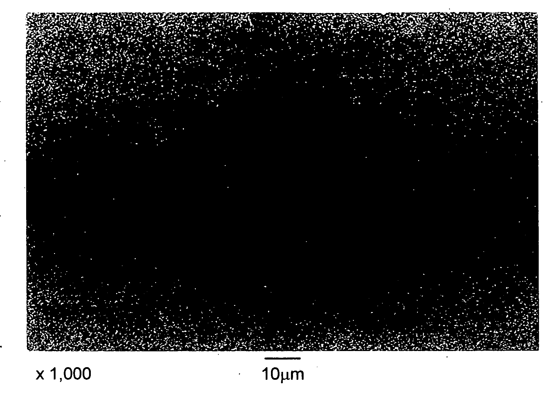
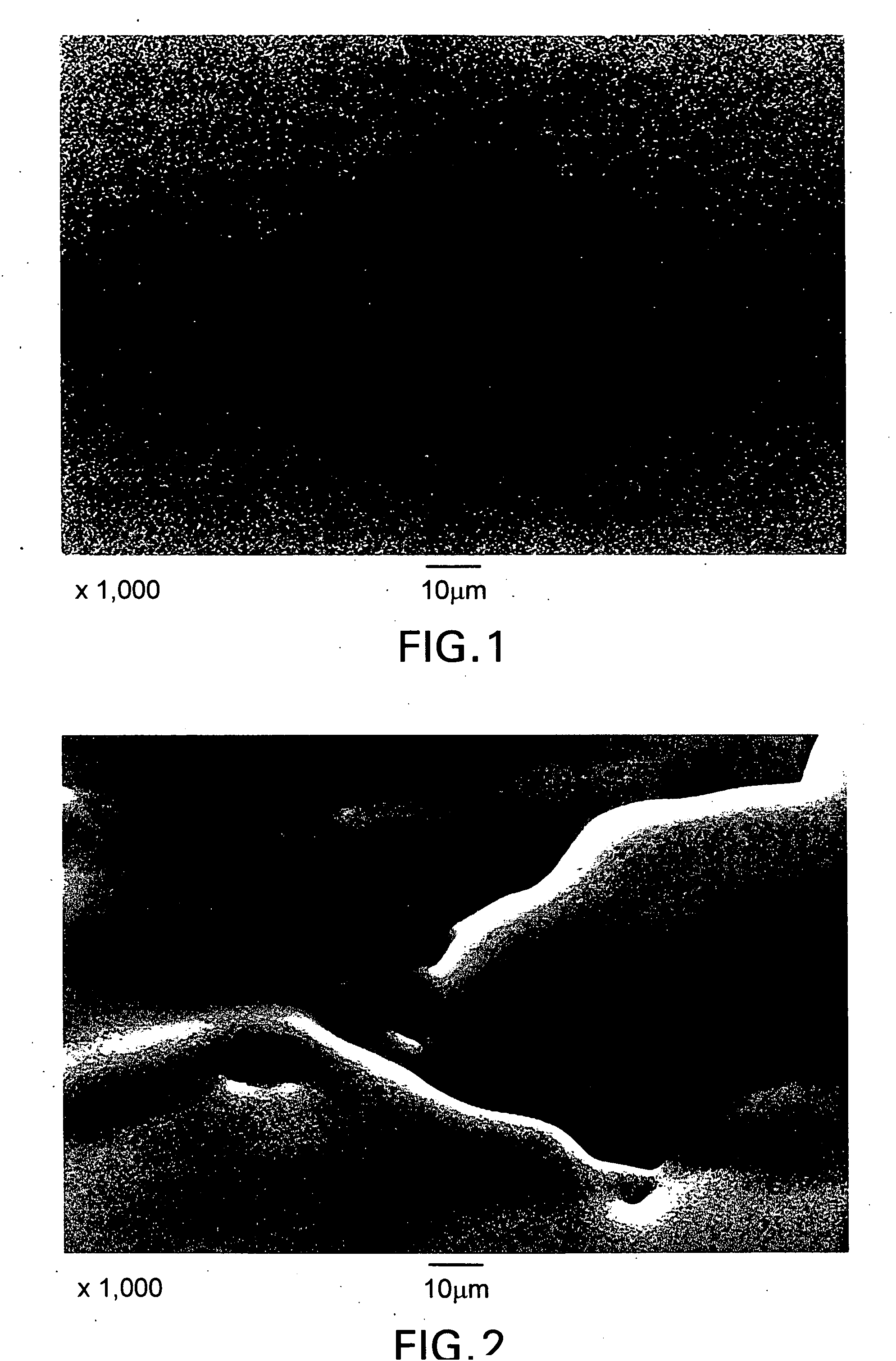
The resultant electrodeposited copper foil had low roughness on the roughness surface of the electrodeposited copper foil, however, moderate uneven surge still occurred on the roughness surface (see FIG. 7 below).
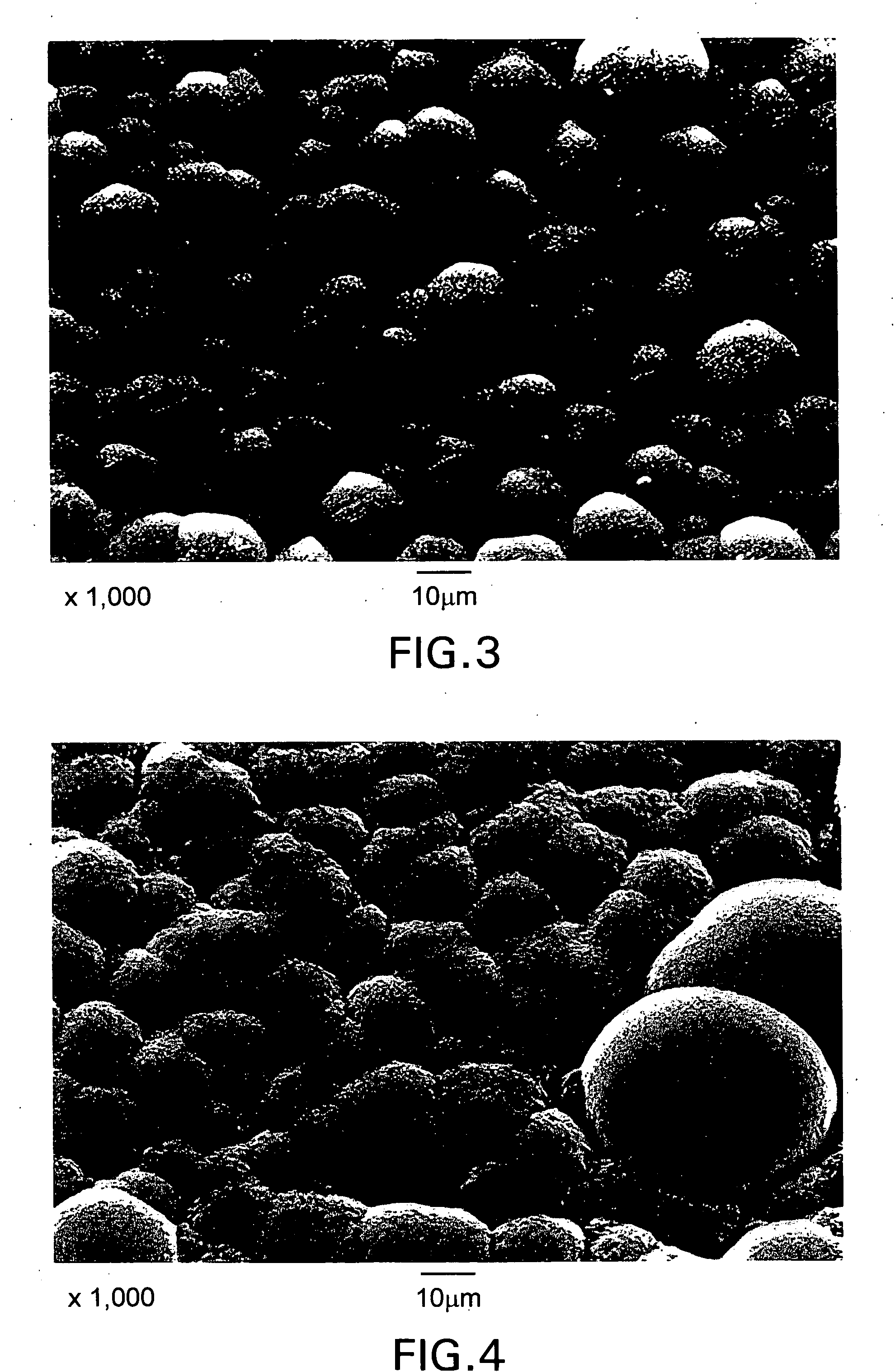
The moderate uneven surge occurring on the roughness surface of the electrodeposited copper foil (electrodeposited copper foil, without treatment) may induce abnormal precipitation of copper crystalline particles during the aforementioned step of providing roughness, and increase surface roughness (Rz) of a roughness surface of product.
In application of flexible printed-wiring board, a copper foil undergoes heat history in the step of adhesion with an insulating film, and when copper crystalline particles are small in size, they will grow and become bulky through this heat history.

Method used


Image

  • Electrolytic copper foil with low roughness surface and process for producing the same
  • Electrolytic copper foil with low roughness surface and process for producing the same
  • Electrolytic copper foil with low roughness surface and process for producing the same

Examples


Embodiment Construction

[0051] Best mode for carrying out the invention will be described below.

[0052] An electrolyte of an aqueous solution of sulfuric acid / copper sulfate comprising 100 g / L of sulfuric acid (H2SO4) and 280 g / L of copper sulfate pentahydrate (CuSO4.5H2O) was prepared (hereinafter, this electrolyte is referred to as “basic electrolyte”).

[0053] As additives, polyethylene glycol (average molecular weight 20000, product of Sanyo Chemical Industries, Ltd.), polyethyleneimine (“EPOMIN (product name), Product number: P-1000, Nippon Shokubai Co., Ltd., weight average molecular weight: 70000), sodium 3-mercapto-1-propane sulfonate, and hydrochloric acid were added to the basic electrolyte such that 30 mg / L of polyethylene glycol, 0.5 mg / L of polyethyleneimine, 220 μmol / L of sodium 3-mercapto-1-propanesulfonate and 35 mol / L of chloride ions were achieved.

[0054] The electrolyte containing these additives was allowed to flow between a titanium plate coated with an oxide of Platinum Group serving a...


PUM

PropertyMeasurementUnit
Temperatureaaaaaaaaaa
Lengthaaaaaaaaaa
Fractionaaaaaaaaaa

Abstract

An electrolytic copper foil with low roughness surface whose surface roughness (Rz) is 2.0 μm or less, the surface uniformly provided with low roughness without uneven surge, which electrolytic copper foil exhibits a percent elongation of 10.0% or higher at 180° C. This electrolytic copper foil with low roughness surface can be obtained by a process for producing an electrolytic copper foil, comprising passing a direct current between an insoluble anode consisting of a titanium plate coated with a Platinum Group element or oxide thereof and a titanium drum as a cathode counter to the anode in an electrolyte of an aqueous solution of sulfuric acid / copper sulfate, wherein the electrolyte contains an oxyethylene surfactant a polyethyleneimine or derivative thereof, a sulfonate of active organosulfer compound and chloride ions.

Description

TECHNICAL FIELD [0001] The present invention relates to electrodeposited copper foil with low roughness surface and processes for producing the same, the copper foils having roughness surface uniformly provided with low roughness without uneven surge and being applicable in printed-wiring boards or cathode collectors of lithium secondary battery. BACKGROUND ART [0002] One conventional process for producing an electrodeposited copper foil well known in the art includes passing a direct current between an insoluble anode consisting of a titanium plate coated with a Platinum Group element or oxide thereof and a titanium drum as a cathode counter to the anode in an electrolyte of an aqueous solution of sulfuric acid / copper sulfate to allow electrodeposited copper to precipitate on the surface of the titanium drum, while peeling off the precipitated electrodeposited copper from the surface of the titanium drum rotating at a constant speed and continuously winding up the same. [0003] In t...

Claims


Application Information

Patent Timeline
IPC IPC(8): C25D3/38C25D1/04H05K3/38
CPCC25D1/04C25D3/38H05K3/384H05K2201/0355H05K2203/0307H05K2203/0723
Inventor SANO, YASUSHISAKON, KAORUAKAMINE, NAOSHI
Owner FUKUKA METAL FOIL & POWDER CO LTD
Learn More