Hydraulic-compression power cogeneration system and method

a cogeneration system and compression power technology, applied in the field of cogeneration systems, can solve the problems of system energy inefficiency, unstable medium that cools down very quickly, and inefficient forced air, and achieve the effect of low cos

Inactive Publication Date: 2006-09-14
ZABTCIOGLU FIKRET M
View PDF27 Cites 50 Cited by
  • Summary
  • Abstract
  • Description
  • Claims
  • Application Information

AI Technical Summary

Benefits of technology

[0044] As an twentieth feature of the invention, a wear-resistant cogeneration system that by eliminating fuel oil, coal or natural gas burning, and by making use of a frictionless material, makes it possible to have a system of long-lived plant.
[0045] As a twenty-first feature of the present invention, for first and second embodiments to provide a cogeneration system with a second embodiment hydrogen mass production means, which are subject of a low cost OEM production and can be compatible to existing central-district residential and/or commercial heating and/or power generation, with regards to technical means and labor, and accordingly is then subject of reasonable prices of sale to the co

Problems solved by technology

Forced air is very inefficient—as it heats the space disproportionately and air is an unstable medium that cools down very quickly, especially as compared to water or steam based systems for example.
These systems are energy inefficient.
Due to the need for dual burners, such systems are large size and therefore are costlier.
These systems that are based on the conventional combustion to provide heat for space heating as well as service hot-water heating and are inefficient.
The instantaneous systems are very energy inefficient and require ignition and switching devices.
Lower durability is a common problem with these systems.
Capital cost that is low: Pow

Method used


Image

  • Hydraulic-compression power cogeneration system and method
  • Hydraulic-compression power cogeneration system and method
  • Hydraulic-compression power cogeneration system and method

Examples


Embodiment Construction

)

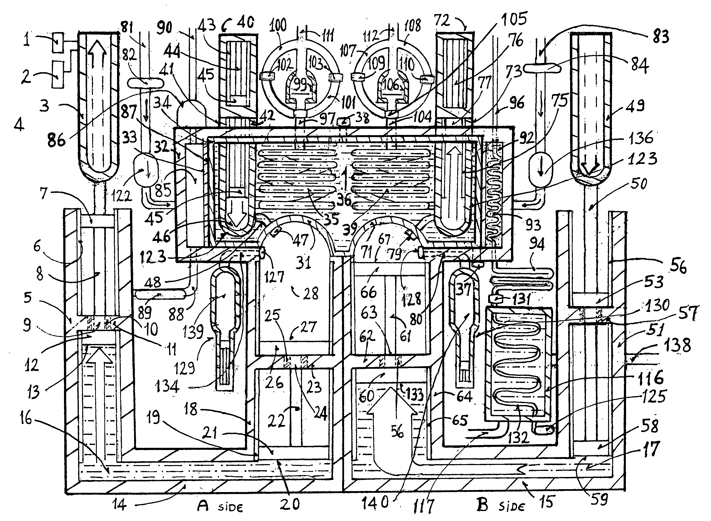
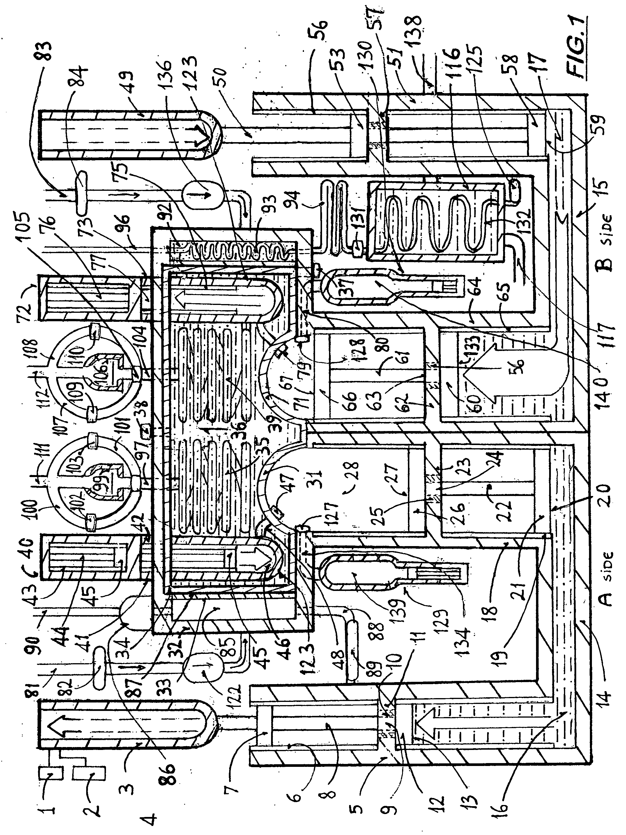
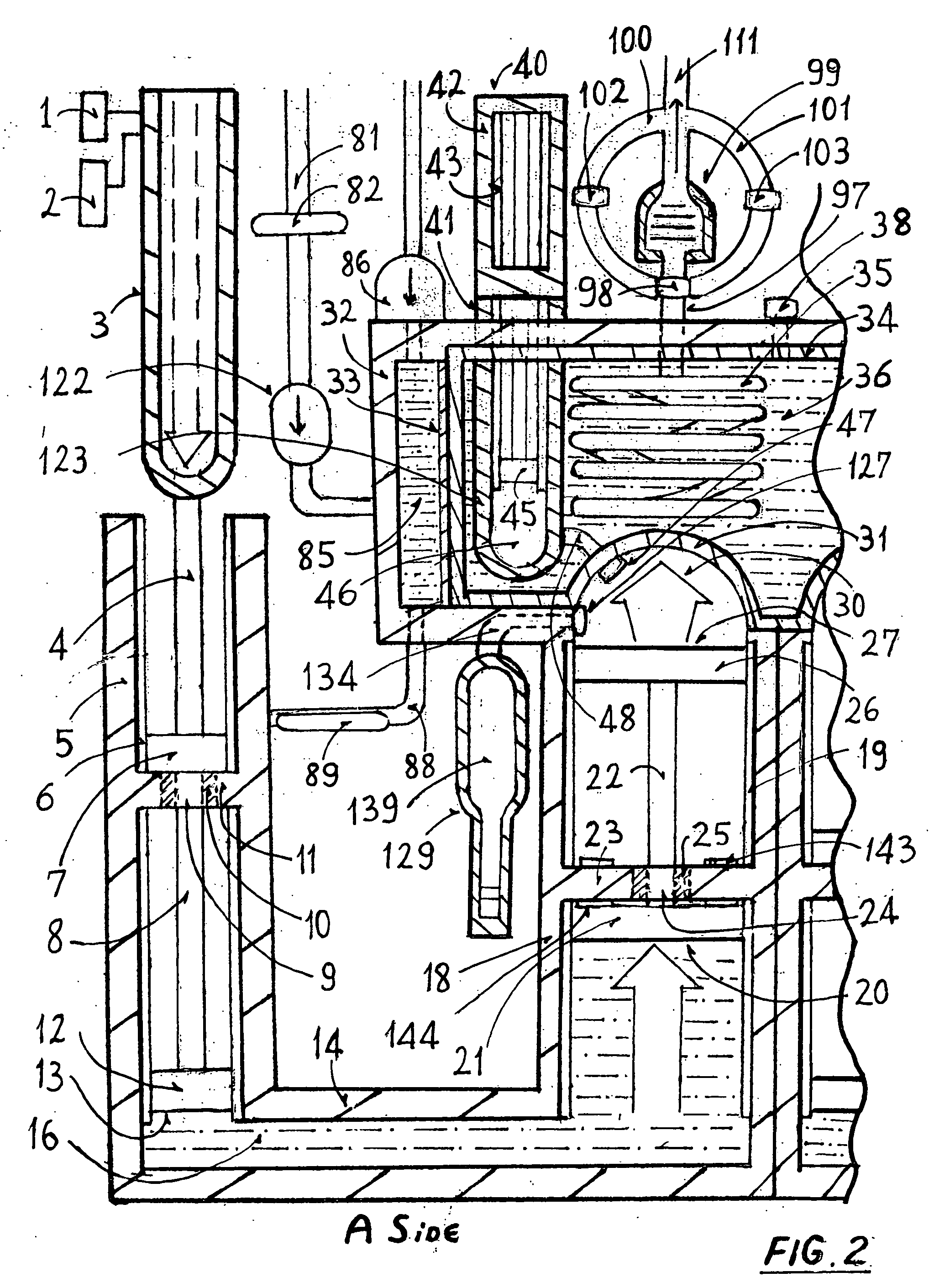
[0207] This invention is based on the following principles of physics:

1. The non-compressibility of fluids in an enclosed container with oil, especially the Pascal hydraulic which is a force multiplier device;

[0208] 2. Compressibility of gases, especially of a gas of low density and high compressibility (Initially adiabatic, then iso-volumetric.) An industrial gas mixture of which the temperature can be increased adiabatically to said high temperatures and has better thermal stability-slower cooling, can be applied instead of air for higher efficiency;

[0209] 3. High temperature thermal storage reservoir that, depending on the engineering choices and material availability would consist of one of the following: A static oil volume of hydrocarbon or carbon-tetrachloride type fluid, or molten nitrate salt or combined molten salt and oil / rock, or liquid sodium or sodium chloride or one similar chemical variant that is highly stable and durable under continuous high temperature and h...


PUM


Abstract

A system and method for converting kinetic energy into useable thermal energy by means of a gas compression based cogeneration. Kinetic forces applied, that are coupled to kinetic components of electro-mechanic thrusters 3, 49-input side, and upper small area pistons 7, 53-receiving side transmitted by shafts 4 and 50 get multiplied through Pascal hydraulic oil links 16 and 17, that are between the lower side small area pistons 12, 58 and lower side large area pistons 21, 60. At least two compression chambers are used to compress gas therein repeatedly to increase the pressure and temperature of the same. Auxiliary compressors 41, 73 help to increase temperature of compressed gas further. Said heat generated is conducted into a single liquid sodium thermal storage volume 36 that facilitates a highly stable thermal storage volume and contains working gas spiral sections 35, 39 circulating within. Steam 113 generated within spiral sections 35, 39 generates power in turbines 99, 106 and then heat residential and/or commercial buildings 115. Service hot-water is provided utilizing a water tank 85 and refrigerant coil circulation oil volume 92, both utilize thermal storage volume 36 waste heat by conduction for a triple integrated system. The system may also be combined with other power generation systems. In second embodiment 121 with more than two units of compression chambers and higher capacity, low cost electric power generated enables efficient hydrogen mass production. A thermo-physical cogeneration system with central heating means, and a cogeneration power plant 121 with hydrogen mass production and hydrogen storage capabilities; are presented as what are new in the art.

Description

[0001] This is a continuation in part application of U.S. patent application (Ser. No. 11 / 006,351) filed on Dec. 7, 2004.BACKGROUND OF THE INVENTION [0002] 1. Field of the Invention [0003] The present invention relates to cogeneration systems, and more particularly to cogeneration systems with central heating. The heating system is combined with a chilled-water central air conditioner to provide an integrated triple system with air conditioning, steam based central heating and service hot-water. A second embodiment relates to a plant of cogeneration power generation and hydrogen mass production capabilities. [0004] 2. Description of the Related Art [0005] Housing apartment units and multi-family units usually use a central heat source such as a boiler or a forced-air system using gas fired or electric resistance furnaces for space heating. Forced air is very inefficient—as it heats the space disproportionately and air is an unstable medium that cools down very quickly, especially as...

Claims


Application Information

Patent Timeline
IPC IPC(8): F02G1/04
CPCF01K17/02F22B3/00Y02E20/14
Inventor ZABTCIOGLU, FIKRET M.
Owner ZABTCIOGLU FIKRET M
Why Eureka
Try Eureka