HVAC system with powered subcooler

a subcooler and hvac technology, applied in the field of hvac systems, can solve the problems of limited compressor efficiency, compressor loss, general inability to fully realize the theoretical benefit of the economizer cycle, etc., and achieve the effects of increasing efficiency, increasing efficiency, and increasing capacity

Active Publication Date: 2006-09-14
JOHNSON CONTROLS TYCO IP HLDG LLP
View PDF35 Cites 32 Cited by
  • Summary
  • Abstract
  • Description
  • Claims
  • Application Information

AI Technical Summary

Benefits of technology

[0011] An advantage of the present invention is that the system has a larger capacity than is available with conventional economizer cycles, and operates at an increased efficiency with respect to conventional economizer cycles.
[0012] A further advantage of the present invention is that the additional efficiency and capacity can be provided without complicated equipment or wiring, allowing the system to be manufactured at a relatively low cost. The powered subcooler circuit includes a design having equipment that is readily available and is easily manufactured. In addition, the increased cooling capacity of the system of the present invention offsets at least a portion of the cost of the additional equipment.
[0013] Yet another advantage of the present system is that the addition of powered subcooler systems according to the present invention permits the use of smaller condenser coils, while providing increased cooling capaci

Problems solved by technology

The introduction of moderate pressure refrigerant gas improves the efficiency of the thermodynamic cycle in spite of limited compressor efficiency.
Another limitation is that these approaches require a special port to the compressor to allow the introduction of intermediate pressure gas.
Additional compressor losses associated with this port generally do not allow the full theoretical benefit of the economizer cycle.
Powered subcoolers have seen limited use in low-temperature refrigeration systems, such as in supermarket refrigerators and/or freezers.
), which w

Method used


Image

  • HVAC system with powered subcooler
  • HVAC system with powered subcooler
  • HVAC system with powered subcooler

Examples


example 1

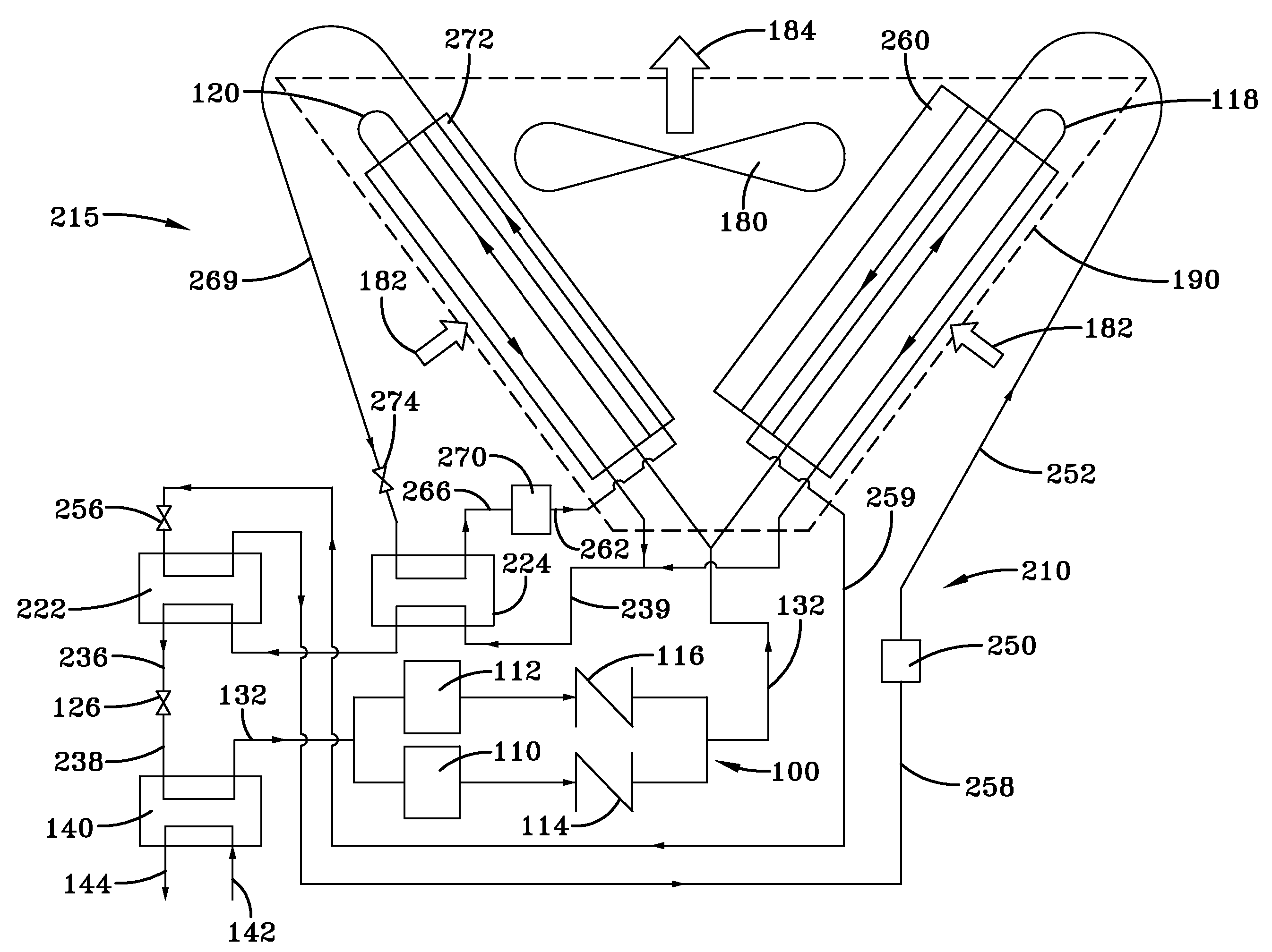
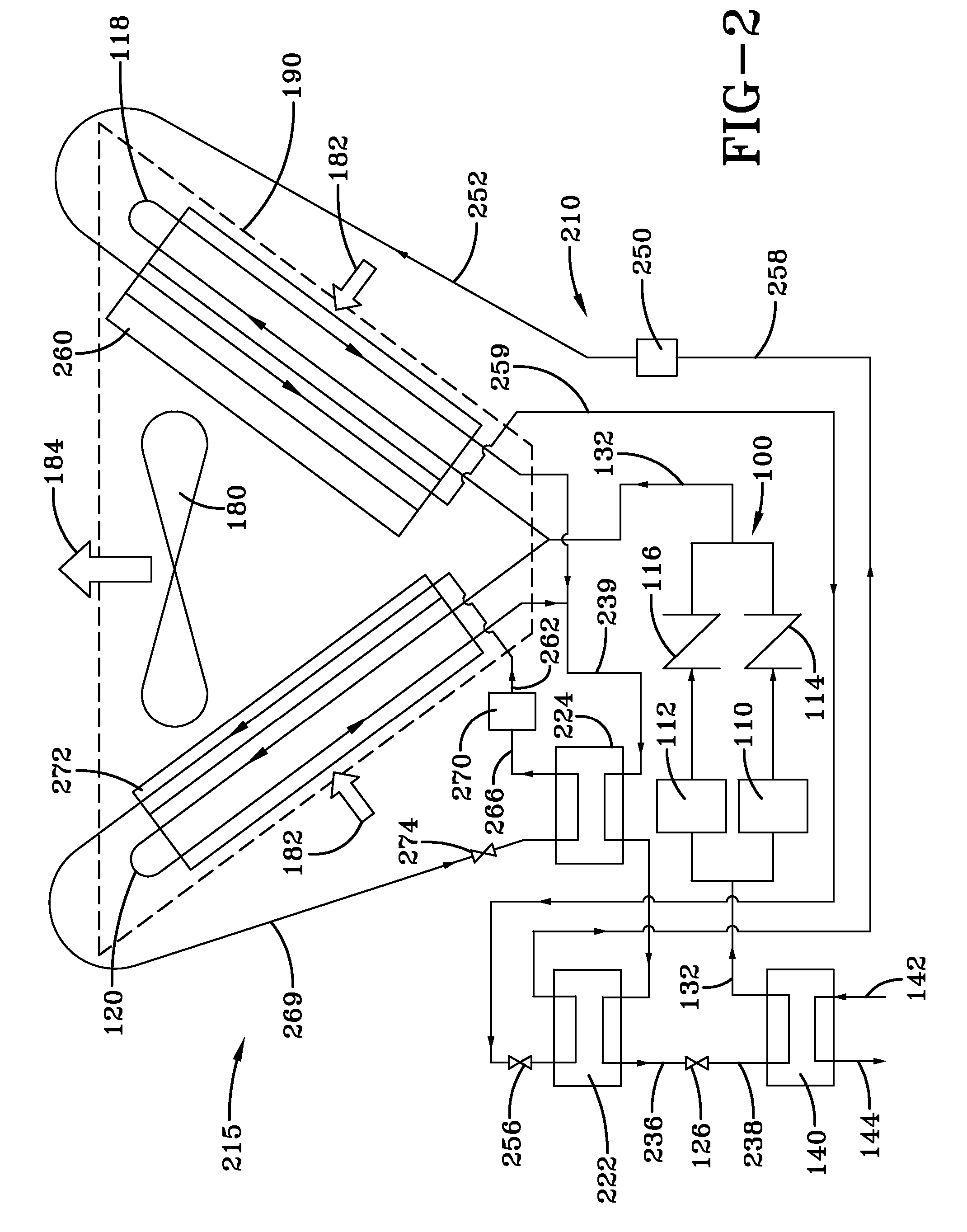
[0048] Example 1 is an embodiment of the present invention, as shown in FIG. 2. The first and second subcoolers 222 and 224 provide subcooling to the refrigerant in the main circuit 100 leaving the condenser 190. Example 1 provides an operating condition that has an evaporating temperature of about 38.7° F. (3.7° C.), which is below the evaporating temperature of Comparative However, the condensing temperature is about 120.3° F. (49.0° C.). The subcooling of the liquid refrigerant leaving the condenser 190 in the main circuit 100 permits the increase in cooling capacity of 25.0% and an efficiency increase of 5.5%. The increase capacity and efficiency permit the fabrication of smaller evaporators and / or the fabrication of smaller condenser units for the same cooling loads.

example 2

[0049] Example 2 is an embodiment of the present invention, as shown in FIG. 2 wherein the system utilizes a larger evaporator than in Example 1. The surface area of the evaporator for the main circuit is increased roughly in proportion to the increase in cooling capacity so as to maintain approximately the same evaporating temperature. The increased size corresponds to the increased capacity that is achieved by subcooling the refrigerant in the main circuit 100. Example 1 provides an operating condition that has an evaporating temperature of about 39.7° F. (4.3° C.). However, the condensing temperature is about 120.7° F. (49.3° C.). The subcooler with larger cooler permits the increase in cooling capacity of 26.8% and an efficiency increase of 6.8%.

[0050] Capacity and Efficiency calculations in Table 2 were based upon the water chiller operating at standard conditions (95° F. ambient temperature, 44° F. leaving water temperature).

[0051] In an alternate embodiment, brine may be uti...


PUM


Abstract

An HVAC system having a main circuit and a subcooler circuit. The main circuit includes a main circuit evaporator, a main circuit expansion device, a main circuit condenser and a main circuit compressor connected in a closed refrigerant loop. The subcooler circuit includes a subcooler evaporator, a subcooler expansion device, a subcooler condenser and a subcooler compressor connected in a closed refrigerant loop. The subcooler evaporator is arranged and disposed to exchange heat between liquid refrigerant in the main circuit and the refrigerant in the subcooler circuit to cool the liquid refrigerant in the main circuit prior to entering the main circuit evaporator. The operation of the subcooler circuit provides an increased cooling capacity per unit of a mass flow of cooling fluid through the main circuit condenser and subcooler condenser for the HVAC system with a predetermined design efficiency.

Description

FIELD OF THE INVENTION [0001] The present invention is directed to an HVAC system. In particular, the present invention is drawn to a chiller system with a powered subcooler. BACKGROUND OF THE INVENTION [0002] Extensive development work spanning many decades has been spent in optimizing the design of commercial air conditioners. [0003] One attempt to optimize commercial air conditioners includes the installation of an economizer. Economizers have been commonly used in screw chillers. A typical economizer introduces refrigerant flash gas from an intercooler to the compressor at a pressure that is between that of the evaporator and the condenser. The introduction of moderate pressure refrigerant gas improves the efficiency of the thermodynamic cycle in spite of limited compressor efficiency. In another attempt to optimize commercial air conditioners, a heat exchanger is used to cool the refrigerant liquid leaving the condenser using refrigerant boiling at an intermediate pressure whic...

Claims


Application Information

Patent Timeline
IPC IPC(8): F25D17/00F25B41/00
CPCF25B6/02F25B7/00F25B9/008F25B13/00F25B40/02F25B2309/061F25B2313/02741F25B2339/047F25B2400/0417F25B2400/075F25B2400/23F25B2600/0251F25B2600/111F25B2700/2106Y02B30/743Y02B30/70F25B9/00
Inventor KOPKO, WILLIAM L.
Owner JOHNSON CONTROLS TYCO IP HLDG LLP
Why Eureka
Try Eureka