
Humidity adjusting film

a film and humidity adjustment technology, applied in the direction of non-metal conductors, cell components, conductors, etc., can solve the problems of difficult prevention of flooding and water tend to condense, and achieve the effects of preventing both dry-up and flooding of the fuel cell, high gas flow rate, and low air utilization ra

Inactive Publication Date: 2006-09-14
JAPAN GORE TEX INC
View PDF4 Cites 17 Cited by
  • Summary
  • Abstract
  • Description
  • Claims
  • Application Information

AI Technical Summary

Benefits of technology

[0015] With the foregoing aspects in view, it is an object of the present invention to establish a technique which makes it possible to prevent both dry-up and flooding of a fuel cell under a broad range of operating conditions ranging from high-humidification conditions to low-humidification conditions, and ranging from a high gas flow rate (low air utilization rate) to a low gas flow rate (high air utilization rate).
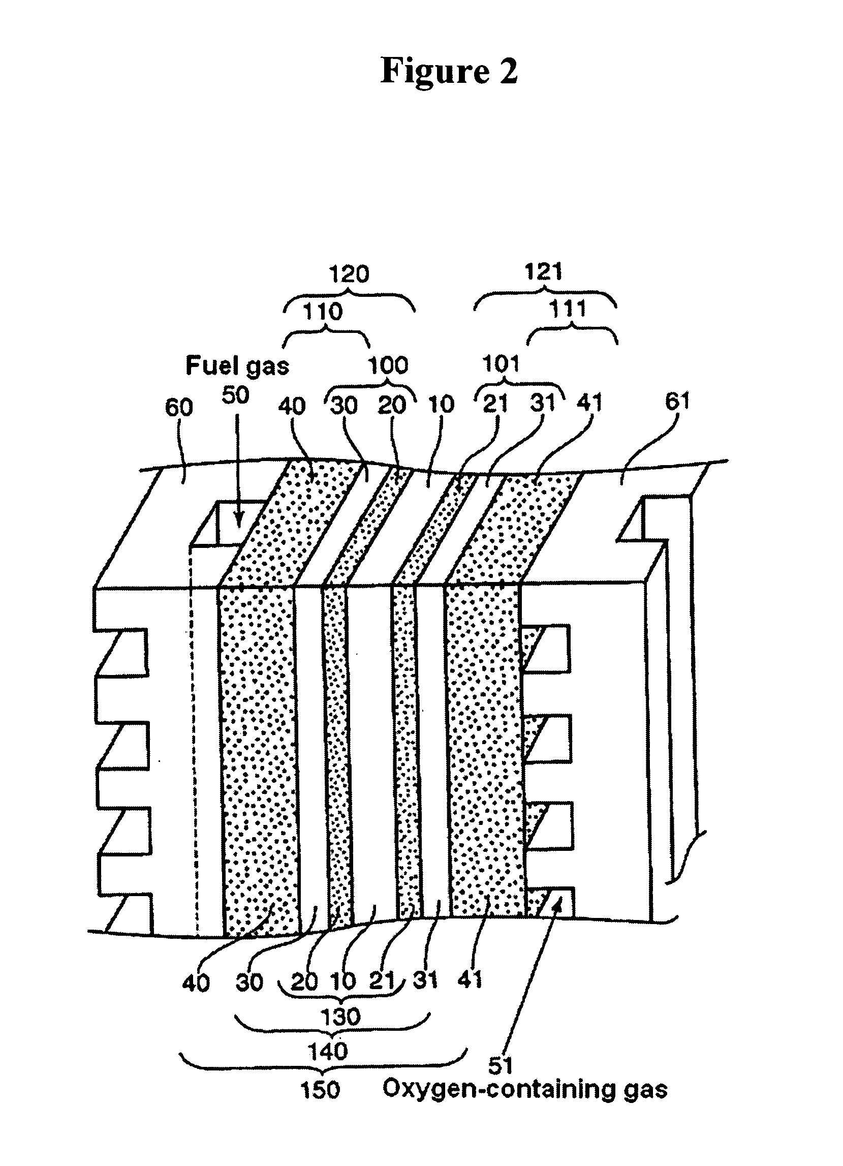
[0024] In the present invention, a mixture of a conductive carbonaceous powder and a polytetrafluoroethylene is formed into a film beforehand, the moisture permeability and thickness of this film are controlled to specified ranges, and this film is sandwiched between a catalyst electrode layer and a carbon fiber collector layer (gas diffusion layer). Accordingly, both dry-up and flooding can be prevented under a broad range of operating conditions ranging from high-humidification conditions to low-humidification conditions, and ranging from a high gas flow rate (low air utilization rate) to a low gas flow rate (high air utilization rate).

Problems solved by technology

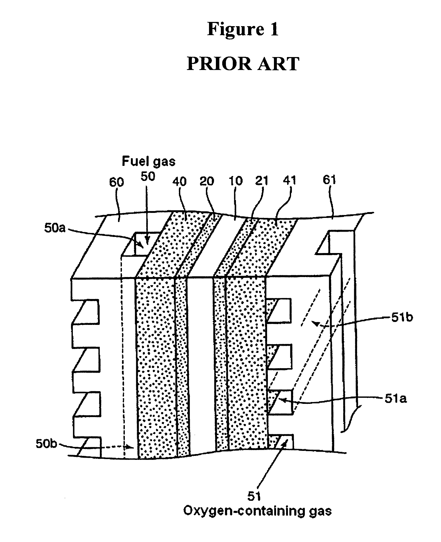
As a result, it was discovered that in the case of the impregnation method, water tends to condense in the large voids inside the carbon fiber collector layer 41, possibly because the carbon fiber collector layer 41, which has an extremely coarse structure, is directly laminated with the catalyst electrode layer 21, so that the prevention of flooding is difficult.

Method used


Image

  • Humidity adjusting film
  • Humidity adjusting film
  • Humidity adjusting film

Examples


working example 1

[0072] Acetylene black (a conductive carbonaceous powder) was placed gently in water so as to prevent scattering, and water was absorbed by the acetylene black while these ingredients were mixed using an agitator. Next, the acetylene black was agitated and dispersed using a homogenizer, thus producing an aqueous dispersion of acetylene black.

[0073] A specified amount of an aqueous dispersion of PTFE (commercial name: D1-E, manufactured by Daikin Industries Ltd.) was added to this aqueous dispersion of acetylene black, and these ingredients were gently stirred by means of an agitator, thus producing a uniform mixed dispersion. Next, the rotation of the agitator was increased, thus causing the co-precipitation of PTFE and acetylene black. The co-precipitate was filtered and collected, and was thinly spread in a stainless steel vat. This co-precipitate was then dried for one day and night at 120° C., thus producing a mixed powder of acetylene black (conductive carbonaceous powder) and...

example of manufacture

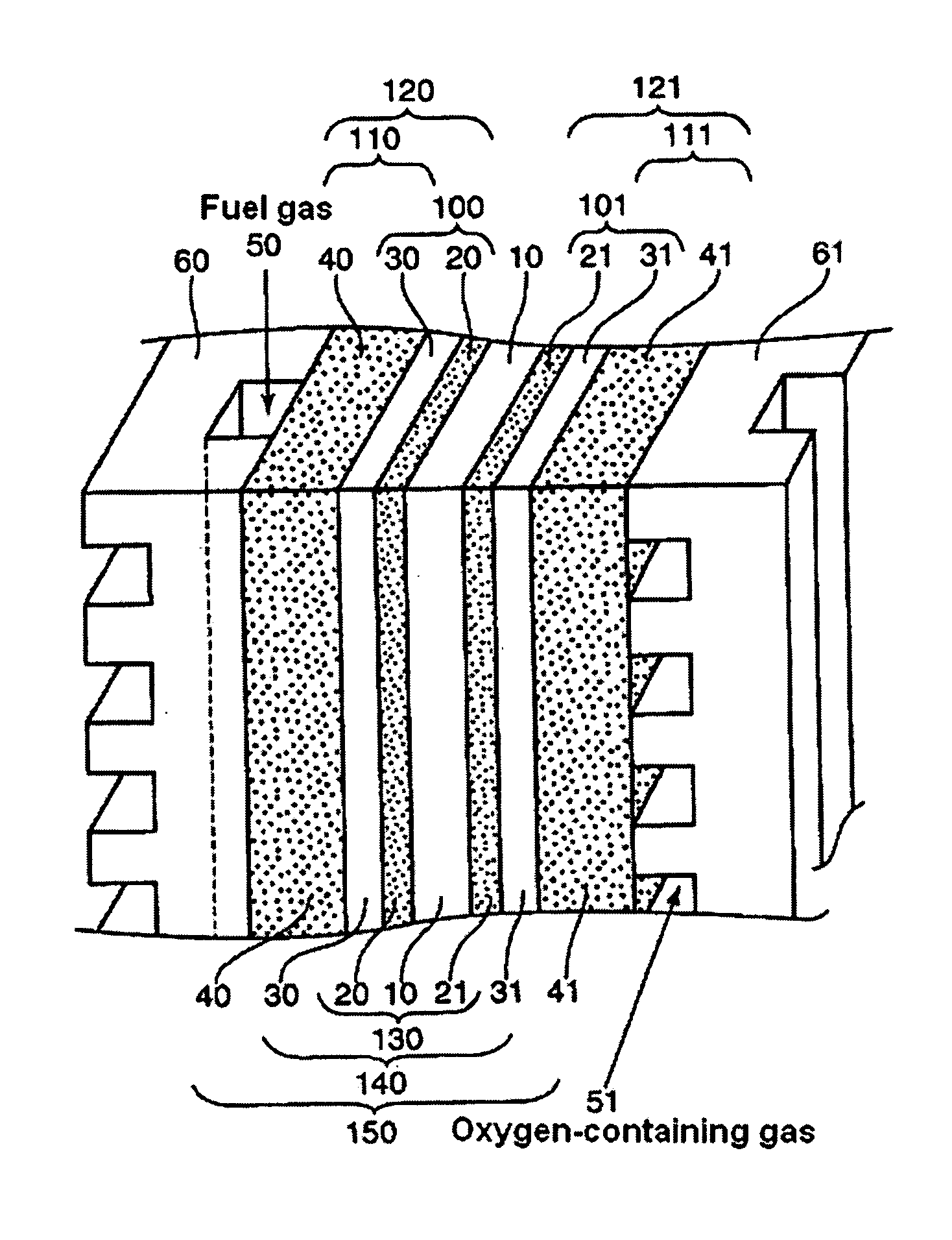
[0083] The single cell shown in FIG. 2 was manufactured using the humidity adjusting films of the working examples and comparative examples obtained as described above. Furthermore, these single cells were manufactured as follows.

Laminated type Gas Diffusion Layers 110 and 111

[0084] A carbon paper (commercial name T-GP-H060, manufactured by Toray) was immersed in a treatment solution adjusted to a PTFE concentration of 10% by diluting an aqueous dispersion of PTFE (commercial name: D1-E, manufactured by Daikin Industries Ltd.) with water, and was then pulled out of this solution. After the excess treatment solution on the surface of the carbon paper was wiped away, the carbon paper was dried for 1 hour at 150° C., and was then subjected to a heat treatment for 2 hours at 350° C., thus producing carbon fiber collector layers 40 and 41 (PTFE content: 18 mass %) subjected to a water-repellent treatment.

[0085] The humidity adjusting films 30 and 31 obtained in Working Examples 1 thro...


PUM

PropertyMeasurementUnit
thicknessaaaaaaaaaa
thicknessaaaaaaaaaa
thicknessaaaaaaaaaa

Abstract

Humidity adjusting films are sandwiched between the catalyst electrode layers and carbon fiber collector layers of a solid polymer type fuel cell. These humidity adjusting films are constructed from a conductive carbonaceous powder and a polytetrafluoroethylene. The moisture permeability as measured by the method stipulated in JIS L 1099 (B-1) is 1200 to 4000 g / m2 hr, and the mean thickness of the films is 5 to 100 μm.

Description

FIELD OF THE INVENTION [0001] The present invention relates to a solid polymer type fuel cell (polymer electrolysis fuel cell (PEFC)). BACKGROUND OF THE INVENTION [0002] In principle, water is the only reaction product of fuel cells that utilize hydrogen and oxygen. Accordingly, such fuel cells have attracted attention as a means of generating clean energy that places little burden on the environment. In particular, solid polymer type fuel cells have seen active research and attempts at practical adaptation, as fuel cells that are easy to handle and that promise to afford an increase in the output power density. Such fuel cells have a broad range of applications; examples include sources of the motive force for mobile bodies such as automobiles and buses, stationary power supplies for general household use, power supplies for compact mobile terminals and the like. [0003] Solid polymer type fuel cells are constructed by stacking numerous single cells; each single cell typically has a...

Claims


Application Information

Patent Timeline
Patent Type & Authority Applications(United States)
IPC IPC(8): H01M4/94H01B1/24H01M4/96
CPCH01M4/8605H01M4/8817H01M4/8896H01M8/0234H01M8/04119H01M8/1004Y02E60/521Y02E60/50
Inventor NOMI, HARUONAMBA, TAKAFUMI
Owner JAPAN GORE TEX INC
Learn More