
Differential steering application for trailer spotter vehicles

a technology for spotter vehicles and steering systems, applied in the direction of non-deflectable wheel steering, transportation and packaging, tractors, etc., can solve the problems of unnecessarily climbing up and down stairs for an extra hundred feet, specialized tractors did not benefit from a low forward entry cab, and added to fatigue, so as to reduce the wall-to-wall turning diameter of tractors, minimal maneuvering space and effort, the effect of improving maneuverability

Inactive Publication Date: 2006-09-21
TAYLOR KERMIT O
View PDF22 Cites 33 Cited by
  • Summary
  • Abstract
  • Description
  • Claims
  • Application Information

AI Technical Summary

Benefits of technology

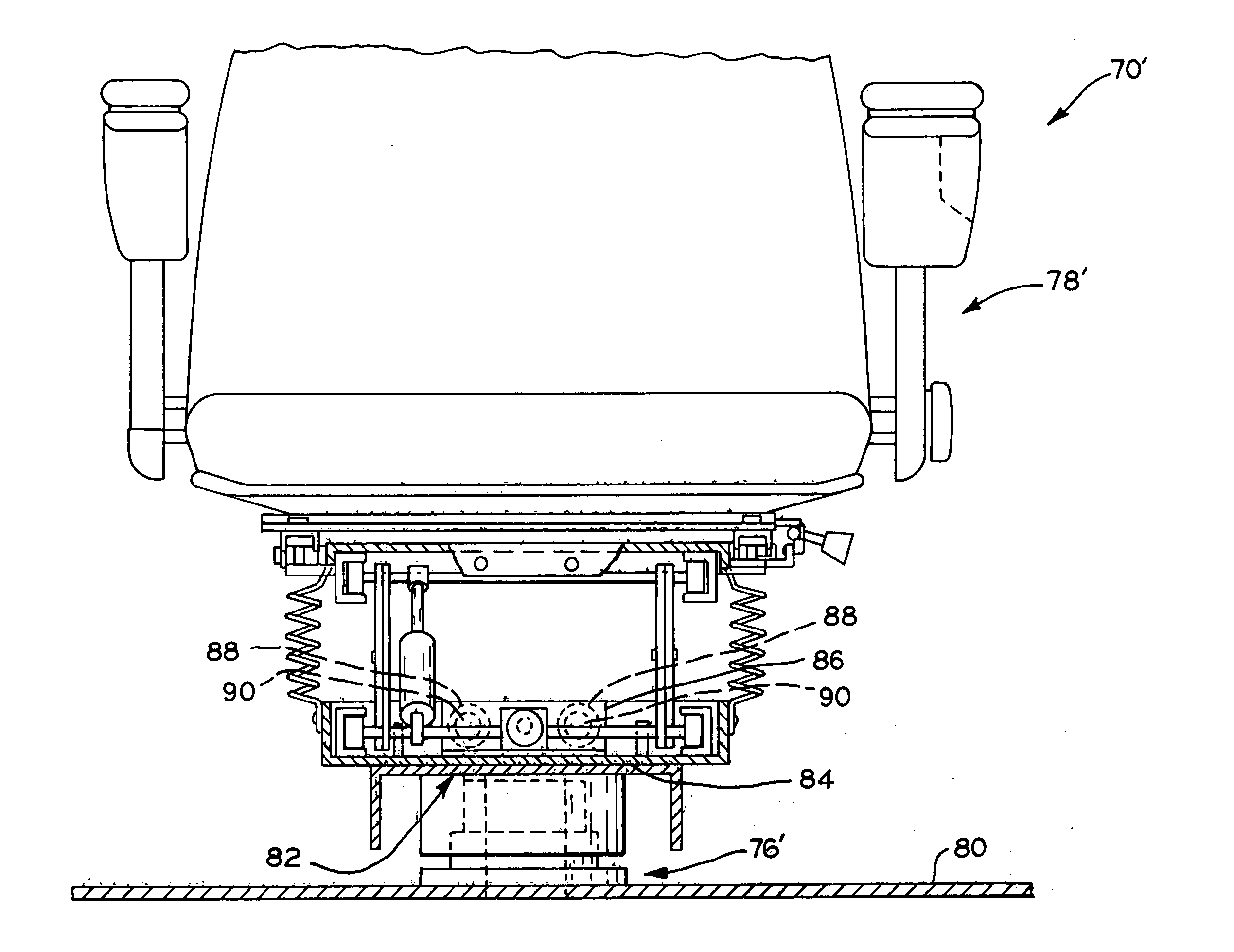
[0012] The present invention includes a trailer spotter vehicle having a seat and a control console which are relatively rotatable with respect to the vehicle frame. The trailer spotter vehicle further includes a differential drive system. The differential drive system permits the vehicle to turn within a very small turning radius while the rotatable seat and control console allow the operator's seat and control console to be positioned such that an operator may steer the vehicle without having to substantially turn their body or use mirrors to observe the path of the vehicle.
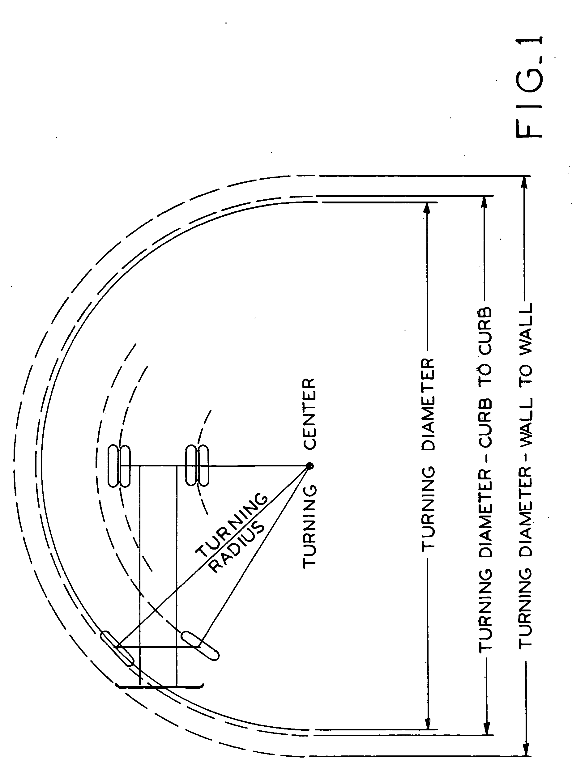
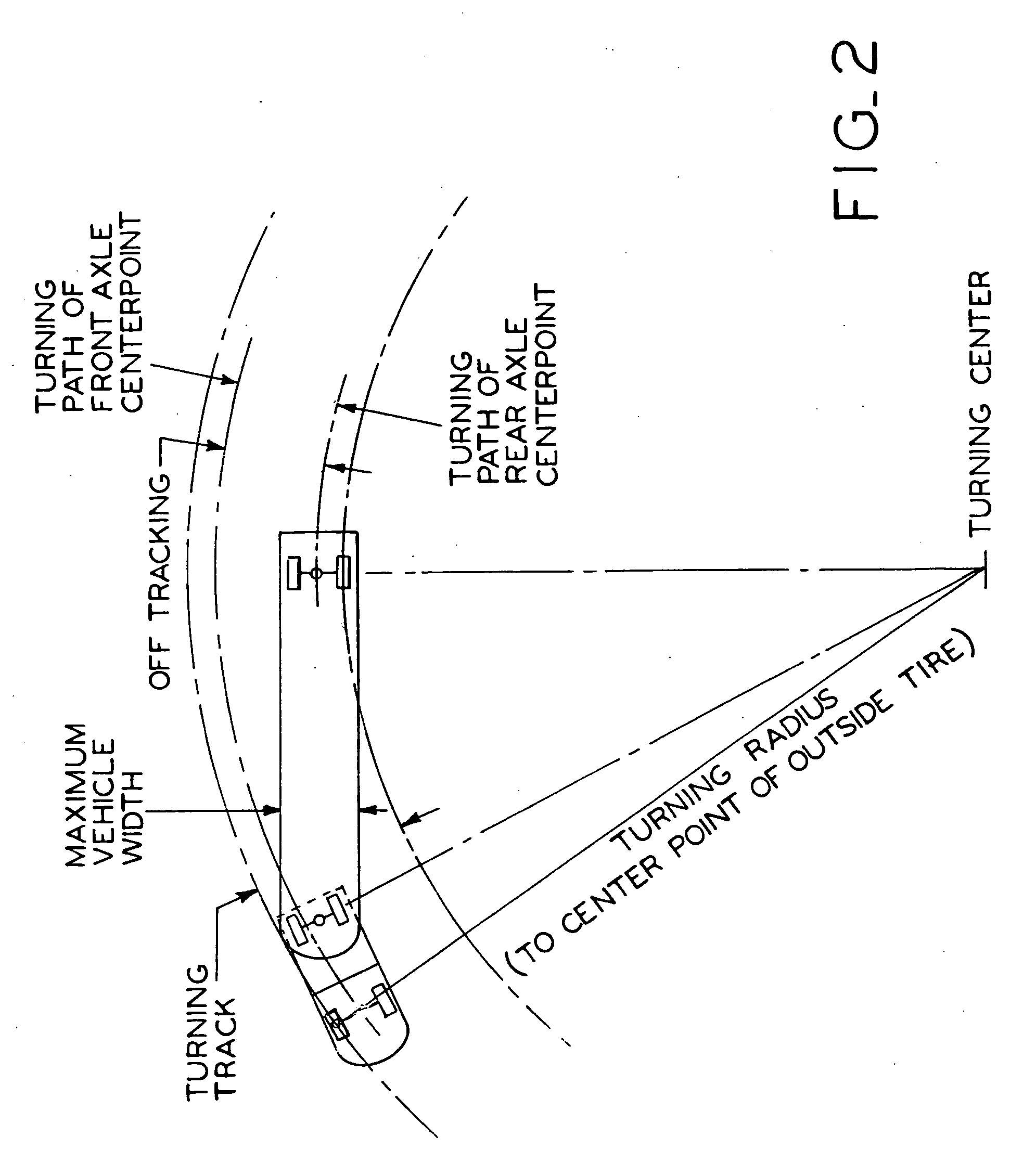
[0013] In one embodiment, the differential drive system includes an engine and first and second hydraulic pumps driven thereby. The first and second hydraulic pumps provide hydraulic fluid to first and second hydraulic motors which are mechanically engaged with first and second ground-engaging wheels, respectively, mounted to the frame of the trailer spotter vehicle. To drive the vehicle in a forward direction, the hydraulic pumps transmit pressurized hydraulic fluid to the motors to drive the wheels in a first direction. In order to drive the vehicle in reverse, the flow of hydraulic fluid to the motors is reversed to rotate the wheels in a direction opposite the first direction. To pivot the vehicle, the first wheel can be driven in the first direction and the second wheel can be driven in the opposite direction in order to substantially turn the vehicle about an axis. Advantageously, the trailer spotter vehicle can be more easily maneuvered than previous trailer spotters.
[0014] The use of differential steering enables the tractor to sharply pivot under a fifth wheel mount between the trailer spotter vehicle and a trailer mounted thereto, or pivot about a point between or near the drive wheels, wherein, as a result, the turning radius is not substantially larger than the wheel base. This design may reduce the tractor's wall-to-wall turning diameter by more than half, but, even more remarkably, as illustrated in FIG. 3, it enables the trailer to be rotated about its rear axle and be backed into a slot / dock position with minimal maneuvering space and effort. Typically, as a result, this improvement in maneuvering can reduce the time required to position a trailer from an average of about 12 minutes to about 8 minutes. Further, the reduction in required maneuvering space will enable more trailers to be stored in a yard, thereby resulting in a corresponding increase in storage capacity. The improved maneuverability of the trailer spotter may also result in less damage to the trailers by making it easier for the operators to adjust the vehicle's position.

Problems solved by technology

Owing to size limitations of these specialized tractors, the cabs were usually mounted on top of the vehicle frame.
Ergonomically, this meant that the operator was unnecessarily climbing up and down stairs for an extra hundred feet every day.
Due to the requirement for tight maneuverability for yard spotters, this additional length was not normally acceptable and, as a result, these specialized tractors did not benefit from a low forward entry cab.
However, opening and closing the door every time the operator stepped onto the deck slowed them down and gradually added to their fatigue.
Accordingly, not only did the operators spend labor hours removing and reinstalling the door, but by the time they went looking for the door in the fall, the door was often damaged or lost resulting in increased maintenance costs to their employer.
A drawback to current trailer spotters includes the standard truck drive train utilized by these trailer spotters.
As a result, the mobility of current trailer spotters is typically limited to a minimum turning radius of approximately 36 feet.
The turn radius of these vehicles is limited by the extent of travel in these linkages and the fact that the drive wheels do not contribute to the turning function.
As a result, maneuvering the tractor and trailer will either scribe a smooth arc over a large area, an unfeasible business expense, or a serpentine course, involving multiple steering adjustments and effort, in a somewhat smaller space.
Additionally, these limitations in maneuverability have recently been exacerbated by longer trailers in service and increases in freight to be handled without corresponding increases in yard space, particularly in established city facilities.
This returns the trailer maneuver difficulty level to previous standards but doubles the number of trips required to reposition all of the trailers.
Further, the operation of a trailer spotter requires an unending series of sudden stops and starts, impact loads, and direction changes.
This results in wear on the mechanical drive train, despite the selection of heavy duty components.
As a result, even with a good maintenance program, vehicle service life seldom extends beyond fifteen years.
This positioning limits cab design options and results in little weight over the drive wheels.
Another instance where existing trailer spotters lack optimization is the operator interface.
Also problematic, turning or twisting to see the trailer impedes the operator's ability to turn the steering wheel.
As a result, both techniques slow their performance and complicate their tasks.
These problems occur as a result of the typical mechanical linkages between the operator interface and the vehicle steering and transmission systems which dictate that the driver's seat and control console be fixed in one direction, the typical direction being forward.
In these previous vehicles, though, the control console did not rotate with the seat and, as a result, an additional control console was required thereby adding cost to the vehicle.
From the above information, it is apparent that the prior art trailer spotter vehicles are far from optimized.
However, although freight handling managers have been complaining about inability to keep up with demand, trailer spotter manufacturers have not envisioned the potential enhancements to their product line discussed below.

Method used


Image

  • Differential steering application for trailer spotter vehicles
  • Differential steering application for trailer spotter vehicles
  • Differential steering application for trailer spotter vehicles

Examples


Embodiment Construction

[0042] Referring to FIGS. 4-6, trailer spotter 30 of the present invention includes cab 32 and frame 34. Trailer spotter 30 further includes differential drive system 36 mounted to frame 34 which is operatively engaged with left rear wheels 38 and right rear wheels 40. Frame 34 further includes an engine cradle which houses engine 39, multi-pump drive 41, variable displacement hydraulic pumps 43 and 45, hydraulic radiator 47 and turbocharger intercooler 49 of differential drive system 36. In operation, air flows through turbocharger intercooler 49 into engine 39 to facilitate combustion therein, as is known in the art. Trailer spotter 30 further includes fuel tank 51, for storing fuel for engine 39, and hydraulic tank 53, for storing hydraulic fluid for differential drive system 36.

[0043] Trailer spotter 30 further includes engine cover 59 mounted above engine 39. Engine cover 59 is rotatable about pillow block bearings 61 to provide access to engine 39. Engine cover 59, when it is...


PUM


Abstract

A trailer spotter vehicle having a seat and a control console which are relatively rotatable with respect to the vehicle frame, and a differential drive system which permits the vehicle to turn within a very small turning radius. The rotatable seat and control console allow the operator to steer the vehicle without having to substantially turn their body or use mirrors to observe the path of the vehicle. To drive the vehicle in a forward direction, hydraulic pumps transmit pressurized hydraulic fluid to the trailer spotter wheels to rotate them in a first direction. In order to drive the vehicle in reverse, the flow of hydraulic fluid to the wheels is reversed to rotate the wheels in an opposite direction. To pivot the vehicle, the first wheel is driven in the first direction and the second wheel is driven in the opposite direction.

Description

BACKGROUND OF THE INVENTION [0001] 1. Field of the Invention [0002] The present inventive concept relates to differential drive systems for a vehicle serving as a trailer spotter for semi-trailers or drawbar-type trailers, especially in off-highway environments such as freight terminals, ports, rail yards, warehouses, and factories. [0003] 2. Description of the Related Art [0004] When over-the-road semi-tractors and trailers came into use, the over-the-road semi-tractors were also used to reposition the trailers in freight yards. On average, the time to reposition a trailer in the freight yard required approximately eighteen minutes. Within a few years, non-over-the-road specialized tractors were developed to reduce this time to about twelve minutes. These specialized tractors utilized two features to provide customer value compared to their predecessors—a elevating fifth wheel hitch and a smaller engine. The ability to raise the fifth wheel enabled operators to move trailers withou...

Claims


Application Information

Patent Timeline
Patent Type & Authority Applications(United States)
IPC IPC(8): B62D11/02
CPCB60N2/143B62D11/003B62D11/02B62D33/06B62D49/007B62D53/0871
Inventor TAYLOR, KERMIT O.
Owner TAYLOR KERMIT O
Learn More