Use of nucleic acid mimics for internal reference and calibration in a flow cell microarray binding assay

a technology of flow cell microarrays and mimics, which is applied in the field of high throughput proteomics, can solve the problems of non-uniform assay conditions, non-uniform flow velocity experiences in individual flow streams, and difficult calibration of internal reference, so as to reduce the cross-reactivity between non-complementary sequences, reduce the intensity, and reduce the contact time

Inactive Publication Date: 2006-09-21
HTS BIOSYST
View PDF3 Cites 20 Cited by
  • Summary
  • Abstract
  • Description
  • Claims
  • Application Information

AI Technical Summary

Benefits of technology

[0012] PNAs bind both DNA and RNA to form PNA / DNA or PNA / RNA duplexes. The PNA backbone is not charged and, as such, exhibits strong binding characteristics with DNA and RNA due to the lack of charge repulsion between the individual strands. Also, due to the neutral (uncharged) backbone of the PNAs, no salt is required to favor and / or stabilize the formation of PNA / DNA or PNA / RNA duplexes and therefore, the Tm of the resulting duplex is independent of ionic strength. In this way, the PNA / DNA duplex interaction offers a further advantage over DNA / DNA duplex interactions which are highly dependent on ionic strength. In addition, homopyrimidine PNAs have been shown to bind complementary DNA or RNA forming (PNA)2 / DNA or RNA triplexes of high thermal stability (see, Egholm et al., Science, 254: 1497 (1991); Egholm et al., J. Am. Chen. Soc., 114: 1895 (1992); Egholm et al., J. Am. Chem. Soc., 114: 9677 (1992)).
[0016] The invention described herein provides a fast, reliable, and accurate method for calibrating or normalizing for uncontrollable variations in the signal intensity generated by molecular binding reactions taking place on the surface of a microarray chip as a result of the nonuniform flow rate of a laminar fluid stream in a flow cell cartridge. Specifically, it is known that the flow rate of a fluid stream through a microchannel is faster in the center of the stream and slower at the outer periphery of the stream, due to contact of the laminar fluid stream with, and the resulting friction from, the surfaces of the microchannel, in particular the walls of the channel. As demonstrated herein, this differential in flow rate causes a “false” variation in chemiluminescence intensity between molecular binding reactions taking place on different sections of a single chip.
[0017] The invention described herein provides a method for accounting for variations in fluorescence intensity that result from these variations in flow rate, and thereby improves the accuracy of results obtained from a qualitative or quantitative-type microassay via analysis of the binding reactions of designed nucleic acids, preferably peptide nucleic acids (PNAs), which are advantageously spotted at predetermined locations onto the surface of the microchip and included as part of the assay reaction. In particular, a homologous population of peptide nucleic acids are immobilized or “spotted” onto a microarray chip at one or more predetermined locations. Preferably, at least two or more spots of PNAs are arranged in a contiguous row or, more preferably, a contiguous column on the surface of the microarray chip. More preferably, the at least two or more spots of these PNAs are arranged in a column that is perpendicular to the flow of fluid across the surface of the microchip. Preferably, a first population of PNA oligos is spotted on a section of the microchip that is closer to the walls of the cartridge and a second population of PNA oligos is spotted closer to the center of the microchip, i.e., farther from the walls of the cartridge. According to this arrangement, and as described above, the first population of PNA oligos spotted close to the walls of the cartridge will be exposed to a portion of the reagent stream that is flowing slower than the portion of the reagent stream contacting the second PNA population spotted at the center of the chip. Most preferably, the microchip includes at least three populations of PNA oligos spotted in a line perpendicular to the flow of reagent and arranged such that one population of PNA oligos is spotted on a section of the microchip that is close to one wall of the cartridge and a second PNA population is spotted on a section of the microchip that is closer to the opposite wall of the cartridge from where the first PNA population is located and a third PNA population is spotted near the center of the microarray chip, i.e., farthest from either wall of the cartridge. According to this physical arrangement, the spots positioned by the wall of the cartridge will each be exposed to a portion of the reagent stream that is flowing at a slower rate than the center portion of the reagent stream.
[0021] In a particularly preferred embodiment, a unique population of homogenous nucleic acids is deposited on the chip in a column of at least 4 individual spots spanning the surface of the chip and positioned so as to be perpendicular to the flow of reagent across the surface of the chip. (See, e.g., FIG. 2.) The specificity of the duplexes formed by each of the paired capture and detection nucleic acid sequences is controlled so that the cross-reactivity between non-complementary sequences is minimized, assuring that the signal produced at a given calibration reaction spot is produced by the hybridization of only the “detection” sequence in the reagent that is complementary to the immobilized “capture” sequence that makes up the calibration reaction spot (to the extent of the efficiency of the synthesis of the oligomers).
[0025] According to the present invention, each of the one or more reservoirs of the flow cell cartridge that will include a fluid reagent for use in a particular microassay may include at least one unique homogenous population of calibration molecules dispersed in the reagent. By “unique” it is meant that the nucleic acid sequence of the calibration molecule in any given reservoir is different from the nucleic acid sequence of any calibration molecule in any of the other reservoirs, so as to prevent the unwanted binding / interaction of calibration molecules from different reservoirs during the running of the assay and, more importantly, to provide a method for calibrating or normalizing reactions carried out with reagents from each reservoir, whether the reagent contains an analyte or is simply a wash buffer or other reagent without analyte. It should also be noted that any reservoir reagent may include more than one homologous population of nucleic acid molecules again, as long as each reservoir has its own unique population of nucleic acid molecules and as long as the different populations in each reservoir do not interact or have very low, preferably zero, binding affinity for each other.
[0028] In another embodiment, this method is also suitable for calibrating or normalizing for differences observed between similar microarray assays performed in different flow cell cartridges or variations between similar binding reactions performed on different, i.e., separate, microassay sensor chips. In addition to the surface effects that exist in a flow cell cartridge as described above, slight manufacturing differences between (otherwise identical) cartridges can also affect the rate of laminar flow from one cartridge to the next. Therefore, as described in more detail below, the present invention is also suitable as a fast, accurate, and reliable method for accounting for variations in microassay binding results that occur with similar reactions carried out in two or more flow cell cartridges.

Problems solved by technology

Control of fluid movement through the microfluidic cartridges is particularly problematic because of the microscale nature of the device.
Proper control of fluids through flow paths is a challenge, as microdimensions impart characteristics and behaviors that are not encountered in larger scale fluidic systems, due primarily to the greater influence of surface effects within the flow cell cartridge in a microscale environment.
For example, one difficulty in a laminar flow assay system is that during pressure-induced flow of fluids through microchannels, non-uniform flow velocities are experienced in individual flow streams due in part to friction that exists at the interface of the reagent and the surfaces of the cartridge during fluid transport.
This differential resistance to flow, particularly over the surface of a functionalized sensor chip, can lead to undesirable, nonuniform assay conditions at the chip surface, where experimental conditions with respect to analyte binding differ on the outer edges of the sensor chip (where fluid flow is slower), as compared to the conditions on the center portion of the chip (where fluid flow is faster).
Controlling the rates of fluid flow through microchannels and reducing the surface effects that a flow cell cartridge has on laminar flow of reagents can be complicated and costly given the microscale nature of any design parameters.
Another method for accounting for the differences in flow rate in a single flow stream would be to monitor the differences in flow rate via a flow meter built into the cartridge, however the costs of such a cartridge would make it prohibitively expensive for most users.

Method used


Image

  • Use of nucleic acid mimics for internal reference and calibration in a flow cell microarray binding assay
  • Use of nucleic acid mimics for internal reference and calibration in a flow cell microarray binding assay
  • Use of nucleic acid mimics for internal reference and calibration in a flow cell microarray binding assay

Examples


examples

Array Fabrication

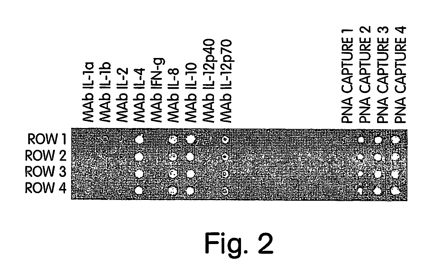
[0092] The following cysteine-modified “capture” PNA oligomers, for use in calibration reaction spots immobilized on a microassay sensor chip according to the present invention, were designed for use as an internal reference and calibration indicator:

Acetyl-Cys-OO-GTAGTCCG,(“Capture 1”; SEQ ID NO:1)Acetyl-Cys-OO-CGAAATGT,(“Capture 2”; SEQ ID NO:2)Acetyl-Cys-OO-GCGTAACT,(“Capture 3”; SEQ ID NO:3)andAcetyl-Cys-OO-TCACAAGC.(“Capture 4”; SEQ ID NO:4)

[0093] The following complementary biotinylated “detection” PNA oligomers, to be added to the reagent reservoirs for use as calibration reagents according to the present invention, were designed to form a duplex with the immobilized “capture” ligands on the chip:

Biotinyl-OO-CGGACTAC,(“Detection 1”;SEQ ID NO:5)Biotinyl-OO-ACATTTCG,(“Detection 2”;SEQ ID NO:6)Biotinyl-OO-AGTTACGC,(“Detection 3”;SEQ ID NO:7)andBiotinyl-OO-GCT-TGT-GA.(“Detection 4”;SEQ ID NO:8)

In the foregoing formulae, “—OO—” represents a polyethylene gly...


PUM

PropertyMeasurementUnit
pHaaaaaaaaaa
affinityaaaaaaaaaa
fluorescenceaaaaaaaaaa

Abstract

The present application describes a method for normalizing for variations in signal intensity observed in a biomolecular binding assay carried out in a flow cell cartridge. Variations in signal intensity occur as a result of the effect of the surfaces of a flow cell cartridge on the laminar flow of reagent through the cartridge. In any individual reagent stream, fluid flows faster in the center of the stream and slower at the outer periphery of the stream due to contact of the reagent with the walls of the cartridge, creating a parabolic fluid flow profile. The present invention describes a method for normalizing or calibrating out the differences in intensity observed in different regions of interest on a single chip or similar reactions carried out in different cartridges, as a result of these differential fluid flow rates. Microarray chips having integrated calibration regions are also described.

Description

CROSS-REFERENCE TO RELATED APPLICATION [0001] This application claims priority to U.S. Provisional Application No. 60 / 451,468 filed Mar. 3, 2003.FIELD OF THE INVENTION [0002] The present invention is related to the field of high throughput proteomics and to equipment useful for the simultaneous analysis of up to thousands of biomolecular interactions occurring on the surface of a single microchip inserted in a flow cell cartridge. In particular, the present invention provides materials and methods for normalizing or calibrating for variations in signal intensity of binding reactions on a microarray chip due to variations in reagent flow rate over the surface of the chip that occur as a result of the contact between the flow stream and the surfaces of the flow cell cartridge. The present invention also provides a method for normalizing or calibrating for differences in signal intensity observed with similar reactions performed on separate chips and / or in different flow cell cartridge...

Claims


Application Information

Patent Timeline
Patent Type & Authority Applications(United States)
IPC IPC(8): C12Q1/68G01N33/53C12M1/34
CPCB01L3/5027B01L2200/148B01L2300/0636B01L2300/0877C12Q1/6813C12Q2565/501C12Q2545/101C12Q2525/107
Inventor LAMBERT, JEREMY
Owner HTS BIOSYST
Why Eureka
Try Eureka