Capture and release assay system and method

a technology of capture and release and assay, which is applied in the field of capture and release assay system and method, can solve the problem of limiting the detection sensitivity of the analyte of interest, and achieve the effect of enhancing the detection sensitivity

a technology of capture and release and assay, which is applied in the field of capture and release assay system and method, can solve the problem of limiting the detection sensitivity of the analyte of interest, and achieve the effect of enhancing the detection sensitivity

US20060211055A1Inactive Publication Date: 2006-09-21CAPLIPER LIFE SCI INC

Image

  • Capture and release assay system and method
  • Capture and release assay system and method
  • Capture and release assay system and method

Examples


Embodiment Construction

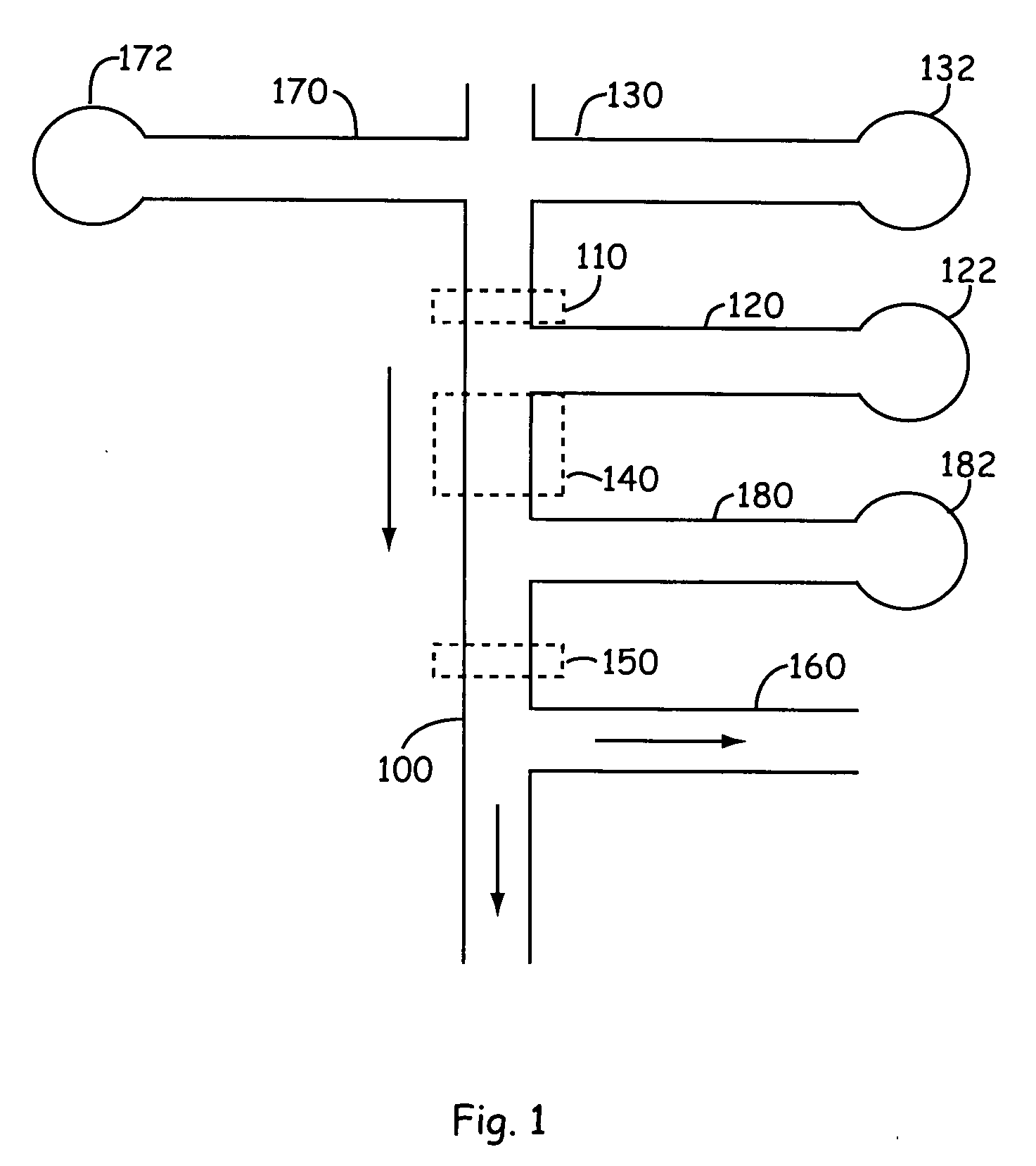
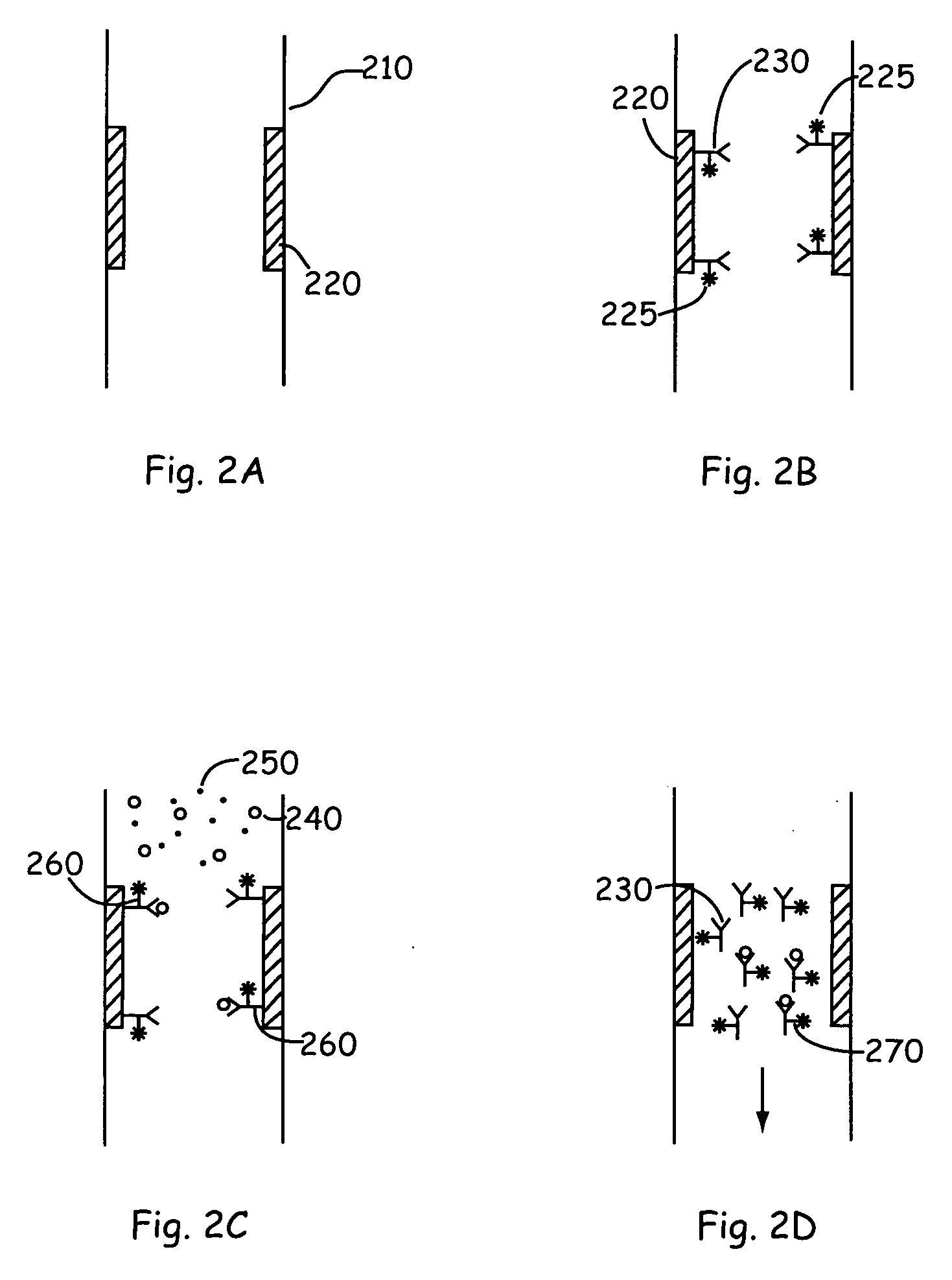
[0024] The present invention provides new technology for detecting a component of interest in a complex sample. The present invention provides methods and microscale devices for continuous flow binding (e.g., capture), release, separation and detection. Prior to separation, the sample is flowed through a binding channel or affinity purification zone in which it is contacted by a moiety that specifically binds the one or more component of interest within the mixture. For example the component of interest is optionally a protein that is detected by a binding reaction with an antibody specific to the protein. The component of interest is detected in the present invention by binding the component of interest to a binding moiety that is specific to the component of interest. The component of interest is optionally a protein, a peptide, a nucleic acid (e.g., an oligonucleotide, DNA, cDNA, or RNA), carbohydrate, or the like. The component is typically included in a complex mixture of vario...


PUM

PropertyMeasurementUnit
diameteraaaaaaaaaa
wavelength rangeaaaaaaaaaa
pHaaaaaaaaaa

Abstract

A method for detecting one or more components of interest in a fluid-borne sample in a microchannel of a microfluidic device includes flowing the fluid-borne sample, in which the one or more components of interest are bound to a first labeled component binding moiety to form a first labeled complex, through a binding channel region of the microchannel. The binding channel region includes a second component-binding moiety reversibly bound to a wall surface of the binding channel region. At least a portion of the one or more components of interest is bound to the second component-binding moiety to form a second labeled complex. The second labeled complex is released from the binding channel region and flowed through a detection channel region of the microchannel, where the second labeled complex is detected.

Description

CROSS-REFERENCE TO RELATED APPLICATION [0001] This application is a divisional of U.S. patent application Ser. No. 10 / 705,211 filed Nov. 7, 2003, which claims the benefit of U.S. Provisional Patent Application No. 60 / 425,582, filed Nov. 12, 2002, both of which are incorporated herein by reference in their entirety for all purposes.BACKGROUND OF THE INVENTION [0002] Analytic detection of biomolecules, e.g., proteins, nucleic acids, and the like, is fundamental to molecular biology. In many applications, it is desirable to detect the presence of one or more particular molecules in a sample. For example, identification of a particular DNA sequence within a mixture of restriction fragments is used to determine the presence, position, and number of copies of a gene in a genome. It is also an integral technique in DNA typing. Analytic detection is also used, e.g., in disease diagnosis and drug development, to determine the presence of a particular antibody or protein, e.g., in a blood sam...

Claims


Application Information

Patent Timeline
21 Sep 2006
Publication
US20060211055A1
IPC
G01N33/53; C12Q1/68
CPC
G01N33/54306
Inventors
HAFEMAN, DEAN G.; WADA, H. GARRETT