Manufacturing method for physical quantity sensor using lead frame and bonding device therefor

a manufacturing method and technology of physical quantity sensors, applied in the direction of acceleration measurement in multiple dimensions, instruments, basic electric elements, etc., can solve the problems of reducing the overall size of the physical quantity sensor chip, sensitivity of the physical quantity sensor will be degraded, and the overall manufacturing cost of the physical quantity sensor can be reduced. , to achieve the prescribed inclination angle with ease, the effect of reducing the overall manufacturing cost and reducing the overall size of the physical quantity sensor

Inactive Publication Date: 2006-09-21
YAMAHA CORP
View PDF3 Cites 11 Cited by
  • Summary
  • Abstract
  • Description
  • Claims
  • Application Information

AI Technical Summary

Benefits of technology

[0044] The adhesion step further includes a chip mounting step and a member mounting step. In the chip mounting step, the physical quantity sensor chip is mounted on the slope of the inclination member. In the member mounting step, the inclination member mounting the physical quantity sensor chip is mounted onto the surface of the stage. This simplifies the manufacturing in that the inclination member on which the physical quantity sensor chip is mounted on the slope is simply mounted on the surface of the stage, which is horizontally held, thus realizing the prescribed inclination angle with ease. Alternatively, the inclination member is mounted on the surface of the stage in the member mounting step; and the physical quantity sensor chip is mounted on the slope of the inclination member in the chip mounting step. In this case, the aforementioned parts of the physical quantity sensor can be easily assembled together in that the inclination member and physical quantity sensor chip are sequentially mounted on the surface of the stage.
[0045] In the above, the inclination member has an adhesive layer having a thermosetting property, which is adhered to the physical quantity sensor chip and the stage respectively; and the adhesive layer is heated and hardened after the inclination member mounting the physical quantity sensor chip is mounted on the surface of the stage. This makes it possible to simultaneously heat the prescribed portion of the adhesive layer directly brought into contact with the physical quantity sensor chip and the other portion of the adhesive layer directly brought into contact with the stage at the same timing, so that the physical quantity sensor chip and stage are firmly adhered to the inclination by way of the hardening of the adhesive layer. This improves the efficiency in manufacturing the physical quantity sensor.
[0046] Alternatively, the inclination member has an adhesion layer having a thermosetting property, which is adhered to the physical quantity sensor chip and the stage respectively; and the inclination member mounting the physical quantity sensor chip is mounted on the surface of the stage which is heated in advance, so that the adhesive layer is heated and hardened by use of heat of the stage. Since the stage is heated in advance, the adhesive layer can be easily heated and hardened just after the inclination member is mounted on the stage. This realizes rapid adhesion between the physical quantity sensor chip, stage, and inclination member. Incidentally, the prescribed portion of the adhesive layer directly brought in contact with the physical quantity sensor chip is positioned slightly apart from the surface of the stage by the intervention of the inclination member and therefore needs a longer time for adhesion and hardening compared with the other portion of the adhesive layer directly brought into contact with the stage. In other words, after the inclination member is mounted on the stage being heated, the physical quantity sensor chip can be reliably mounted on and adhered to the slope of the inclination member because the prescribed portion of the adhesive layer is not hardened rapidly.
[0047] Furthermore, before the physical quantity sensor chip is mounted on the slope of the inclination member, the physical quantity sensor chip can be inclined in advance to be parallel to the slope of the inclination member. Specifically, the physical quantity sensor chip is attached to a collet by way of air suction and is transported toward the slope of the inclination member in such a way that the physical quantity sensor chip is inclined to be parallel to the slope of the inclination member. That is, during the transportation, the physical quantity sensor chip is held substantially parallel to the slope of the inclination member by means of the collet. This reduces positional deviation of the physical quantity sensor chip mounted on the slope of the inclination member. In other words, the physical quantity sensor chip can be mounted on the slope of the inclination member in a stable manner; hence, it is possible to improve the precision regarding the positioning of the physical quantity sensor chip relative to the slope of the inclination member.

Problems solved by technology

This causes a difficulty in reducing the overall manufacturing cost of the physical quantity sensor 380.
However, this causes a difficulty in reducing the overall size of the physical quantity sensor chip.
The sensitivity of a physical quantity sensor will be degraded when the inclination angles of the stages are altered during manufacturing thereof, whereby it becomes difficult to detect bearings and acceleration in a three-dimensional space with a high precision.
In order to incline stages with respect to a frame during manufacturing of a physical quantity sensor, a lead frame may likely be partially deformed, thus causing the inclination angles of the stages to be unexpectedly altered.
This may degrade the precision of setting inclination angles to physical quantity sensor chips; and this may cause difficulty for a physical quantity sensor to accurately detect bearings and acceleration in a three-dimensional space.

Method used


Image

  • Manufacturing method for physical quantity sensor using lead frame and bonding device therefor
  • Manufacturing method for physical quantity sensor using lead frame and bonding device therefor
  • Manufacturing method for physical quantity sensor using lead frame and bonding device therefor

Examples


first embodiment

1. First Embodiment

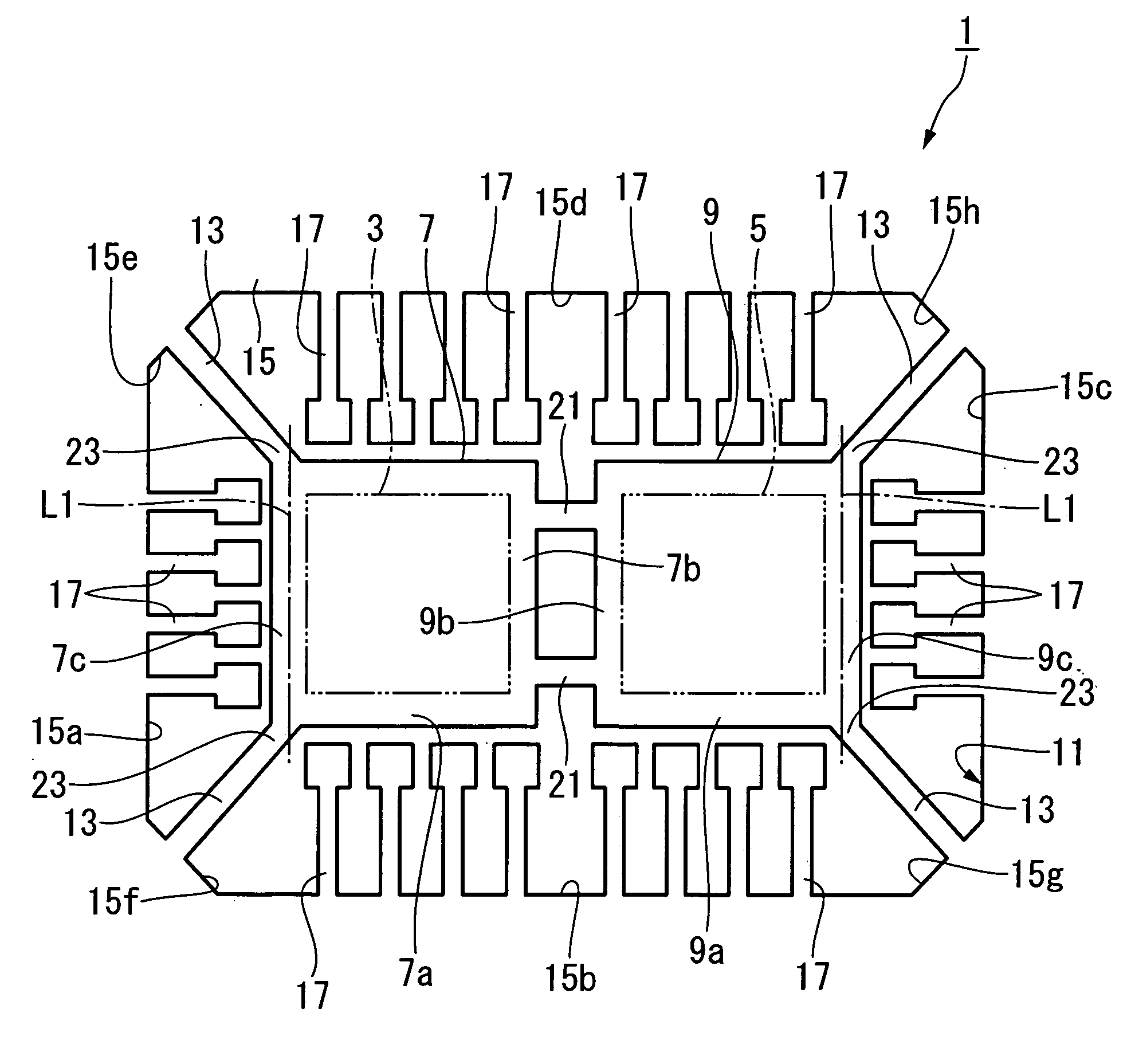
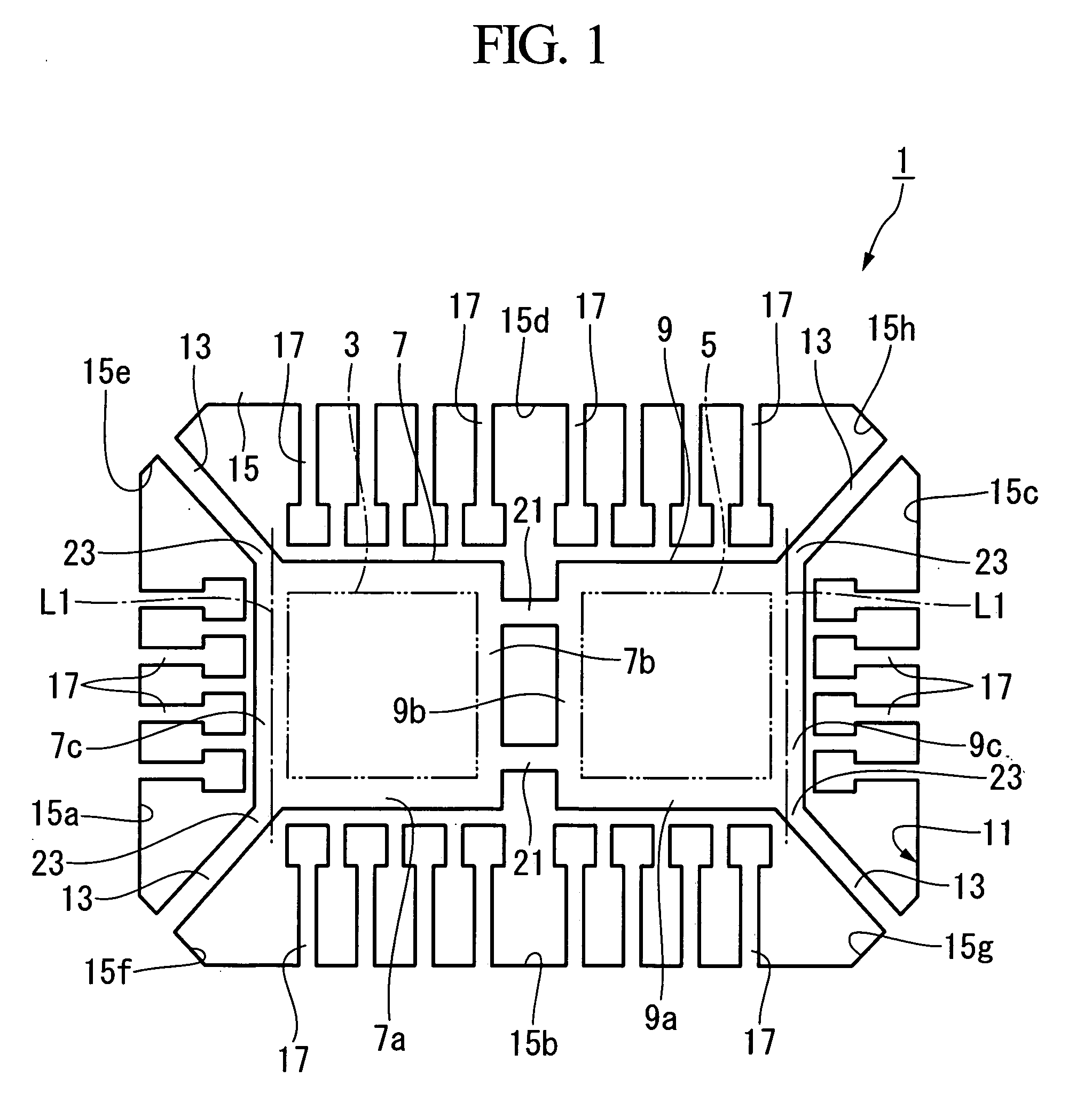
[0099] A first embodiment of the present invention will be described in detail with reference to FIGS. 1-5, 6A, 6B, and 7-9. Specifically, the first embodiment refers to a manufacturing method for a magnetic sensor and a bonding device therefor, wherein it is applied to a magnetic sensor (e.g., a physical quantity sensor) that detects the direction and magnitude of an external magnetic field by use of two magnetic sensor chips mutually inclined with respect to each other. This magnetic sensor is produced using a lead frame, which is formed by performing press working and etching on a thin metal plate composed of cupper and the like.

[0100]FIG. 1 shows a lead frame 1 that includes two stages 7 and 9 having rectangular shapes in plan view for mounting two magnetic sensor chips (or two physical quantity sensor chips) 3 and 5, a frame 11 for supporting the stages 7 and 9, and interconnection leads 13 for mutually connecting the stages 7 and 9 and the frame 11 together...

second embodiment

2. Second Embodiment

[0154] A second embodiment of the present invention will be described with reference to FIGS. 10-14, 15A, 15B, and 16-19. Similar to the first embodiment, the second embodiment refers to a manufacturing method for a magnetic sensor by use of a bonding device.

[0155]FIG. 10 shows a lead frame 101 including stages 107 and 109 having rectangular shapes for mounting magnetic sensor chips 103 and 105, a frame 111 for supporting the stages 107 and 109, and interconnection leads 113 for interconnecting the stages 107 and 109 and the frame 111. All the stages 107 and 109, the frame 111, and the interconnection leads 113 are integrally formed together.

[0156] The frame 111 includes a rectangular frame portion 115 having a rectangular shape in a plan view surrounding the stages 107 and 109, and numerous leads 117 inwardly projecting from four sides 115a to 115d of the rectangular frame portion 115.

[0157] A plurality of the leads 117 are formed with respect to each of the ...


PUM


Abstract

A physical quantity sensor is produced using a lead frame having at least one stage for mounting a physical quantity sensor chip and a frame having leads, wherein the physical quantity sensor chip is inclined with respect to the frame. A bonding device performs wire bonding so as to electrically connect the physical quantity sensor chip and leads, which are respectively located perpendicular to a capillary for discharging wires. The bonding device includes a wedge tool having a first planar surface for holding one ends of wires with leads and a second planar surface for holding the other ends of wires with the physical quantity sensor chip. The lead frame includes interconnection leads, having shape memory alloys, for interconnecting the stage and frame together. The physical quantity sensor chip can be mounted on the stage via an inclination member having a wedge shape.

Description

BACKGROUND OF THE INVENTION [0001] 1. Field of the Invention [0002] The present invention relates to manufacturing methods for physical quantity sensors using lead frames, which detect physical quantities such as bearings, magnetism, gravitation, and acceleration. The present invention also relates to bonding devices for use in manufacturing of physical quantity sensors. [0003] This application claims priorities on Japanese Patent Applications Nos. 2005-66183, 2005-91614, 2005-176221, and 2005-197439, the contents of which are incorporated herein by reference. [0004] 2. Description of the Related Art [0005] Recently, portable terminal devices such as cellular phones having GPS (Global Positioning System) functions for displaying users' positional information have been developed and sold in the open market. In addition to GPS functions, they also have functions for precisely detecting geomagnetism and acceleration so as to detect bearings and moving directions of users in a three-dim...

Claims


Application Information

Patent Timeline
Patent Type & Authority Applications(United States)
IPC IPC(8): H01L21/00H01L23/48H01L23/52H01L29/40
CPCG01P1/023G01P15/18H01L24/78H01L2224/48091H01L2224/49171H01L2224/78301H01L2224/85181H01L2924/00014H01L2224/451H01L24/45H01L2924/181H01L2224/05554H01L2224/48464H01L2224/48472H01L2224/75303H01L24/75H01L2224/75745H01L2224/78803H01L2924/00H01L2224/05599H01L2924/00012
Inventor SHIRASAKA, KENICHISAITOH, HIROSHI
Owner YAMAHA CORP
Why Eureka
Try Eureka