Container box for framed pellicle

Inactive Publication Date: 2006-09-28
SHIN ETSU CHEM IND CO LTD
View PDF8 Cites 12 Cited by
  • Summary
  • Abstract
  • Description
  • Claims
  • Application Information

AI Technical Summary

Benefits of technology

[0021] In the present invention, a pellicle frame can be securedly grasped while keeping contact points to the minimum, which reduces the likelihood of dust generation, and since the frame supporting pin is provided to a container body of increased rigidity, the pellicle is affected little by an external force. Further, in an embodiment in which the container base is made from a plastic resin and a metal component is joined to this container base, the light weight of the plastic resin can be taken advantage of while compensating for the distortion that is a drawback to plastic, allowing just the required portions to be capable of shape retention with respect to external forces.
[0022] In an embodiment in which a component that positions the frame supporting pin that supports the pellicle is mechanically connected to a metal component attached to the container base, the position

Problems solved by technology

In the manufacture of liquid crystal display panels, semiconductor devices such as integrated circuits, and others, a pattern is produced by light exposure of a semiconductor wafer or base glass plate for liquid crystal use, but if dust particles are deposited onto the photomask or reticle used here (hereinafter referred to simply as “photomask”), the dust particles will block or scatter the light, which is a problem in that the fidelity of patterning is lost.
For this reason, this work is usually performed in a clean room, but, even in a clean room of the highest class, it is difficult to keep the photomask in a completely dust-free condition.
Nevertheless, while a pellicle is indeed effective for preventing foreign matter from getting into the closed space formed by the photomask and pellicle once the pellicle has been applied, if any foreign matter has already deposited to the pellicle per se and is present inside the closed space, it becomes very difficult to prevent that foreign matter from being deposited to the photomask surface.
This p

Method used


Image

  • Container box for framed pellicle
  • Container box for framed pellicle
  • Container box for framed pellicle

Examples


Example

WORKING EXAMPLE

[0046] The pellicle containers illustrated in the drawings were constructed.

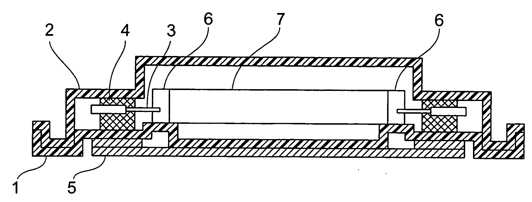
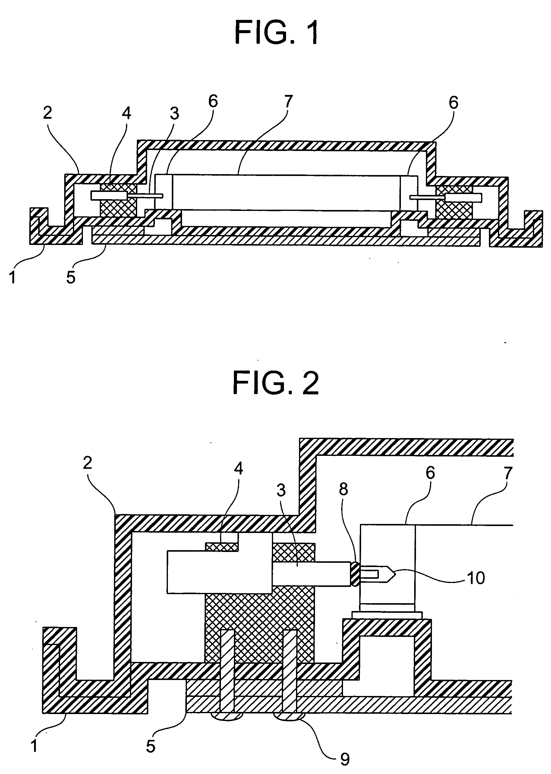
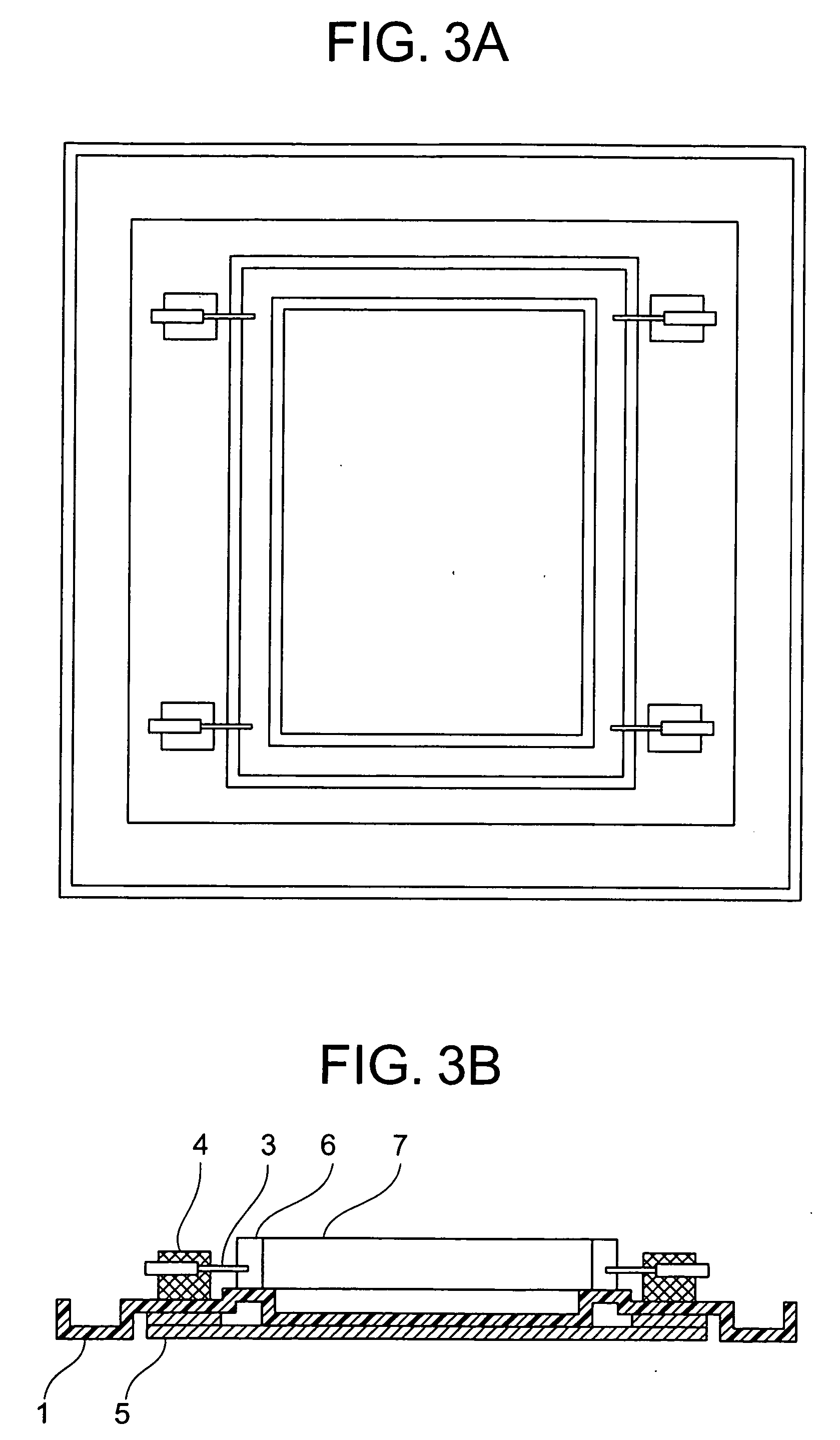
[0047] The pellicle container had a structure mainly composed of the container base 1, which was prepared by vacuum forming of an antistatic ABS resin (Toyolac Parrel TP10 (trade name of Toray); surface resistivity of 5×10¹¹ ohms), and the covering body 2, which was prepared also by vacuum forming of an antistatic ABS resin (Toyolac Parrel TP10, supra); surface resistivity of 5×10¹¹ ohms). The reinforcing metal components 5, which were made from aluminum and had a cross section of 40×6 mm, were disposed on the bottom surface of the container base and five of the reinforcing metal components 5 were connected in the down and across directions as shown in FIG. 4B.

[0048] Furthermore, the reinforcing metal components 5 disposed on the bottom surface of the container base, and the pin fixing components 4 disposed on the upper surface of the container base were mechanically connected by M4 screw b...


PUM


Abstract

There is provided a pellicle container for use in photolithography, with which no dust particles are deposited onto the pellicle contained therein, and contamination of the pellicle can be prevented and good condition is ensured. The present invention provides a pellicle container consisting of a container base on which a pellicle is mounted, and a covering body that covers the pellicle and latches with the container base by engagement together with the container base along the peripheral edges, wherein the pellicle is supported by inserting a frame supporting pin in the opening of a sleeve provided on the outside surface of the pellicle frame. Preferably, the container base is made from a plastic resin and a metal component is joined to the container base; the metal component fixedly connected to the container base is mechanically connected to a positioning component that positions the frame supporting pin that supports the pellicle; and an elastic member is disposed on the point of contact between the frame supporting pin that supports the pellicle and the pellicle frame. It is even more preferable that the container boase and the Icovering body are made of a plastic resin, and these have antistatic performance such that their surface resistivity is no higher than 1×10¹² ohms.

Description

BACKGROUND OF THE INVENTION [0001] The present invention relates to a container box for holding, storing, and transporting a photolithographic pellicle used to shield it against dust deposition in the manufacturing process of semiconductor devices, printed circuit boards, liquid crystal display panels, and the like. [0002] In the manufacture of liquid crystal display panels, semiconductor devices such as integrated circuits, and others, a pattern is produced by light exposure of a semiconductor wafer or base glass plate for liquid crystal use, but if dust particles are deposited onto the photomask or reticle used here (hereinafter referred to simply as “photomask”), the dust particles will block or scatter the light, which is a problem in that the fidelity of patterning is lost. [0003] For this reason, this work is usually performed in a clean room, but, even in a clean room of the highest class, it is difficult to keep the photomask in a completely dust-free condition. This problem...

Claims


Application Information

Patent Timeline
IPC IPC(8): B65D85/48B65D85/38B65D85/86G03F1/40G03F1/64G03F1/66H01L21/027
CPCG03F1/64G03F1/66G03F7/70741G03F7/70983B65D85/38B65D85/42B65D85/48
Inventor NOZAKI, SATOSHISEKIHARA, KAZUTOSHI
Owner SHIN ETSU CHEM IND CO LTD
Why Eureka
Try Eureka