Laser sintering powder recycle system

a technology of laser sintering and recycle system, applied in the field of freeform fabrication, can solve the problems of large floor space occupied by the system, high cost, poor blending of different quality powders, etc., and achieve the effects of reducing part artifacts of poor powder blending, reducing powder loss, and low cos

Inactive Publication Date: 2006-09-28
3D SYST INC
View PDF16 Cites 126 Cited by
  • Summary
  • Abstract
  • Description
  • Claims
  • Application Information

AI Technical Summary

Benefits of technology

[0016] It is an advantage of the present invention that the powder recycle system achieves excellent blending of fresh or virgin powder with overflow and recovered powder to reduce powder loss and achieve consistent and uniform powder quality for use in a laser sintering system.
[0017] It is another advantage of the present invention that part artifacts from poor powder blending are reduced in parts produced in a laser sintering machine utilizing the powder recycle system.
[0018] It is still another advantage of the present invention that a low cost, automated powder handling sys

Problems solved by technology

These systems tend to take up a large amount of floor space and can be expensive because they have to handle large amounts of powder and use mechanical conveying systems such as spiral conveyors to move powder ar

Method used


Image

  • Laser sintering powder recycle system
  • Laser sintering powder recycle system
  • Laser sintering powder recycle system

Examples


Embodiment Construction

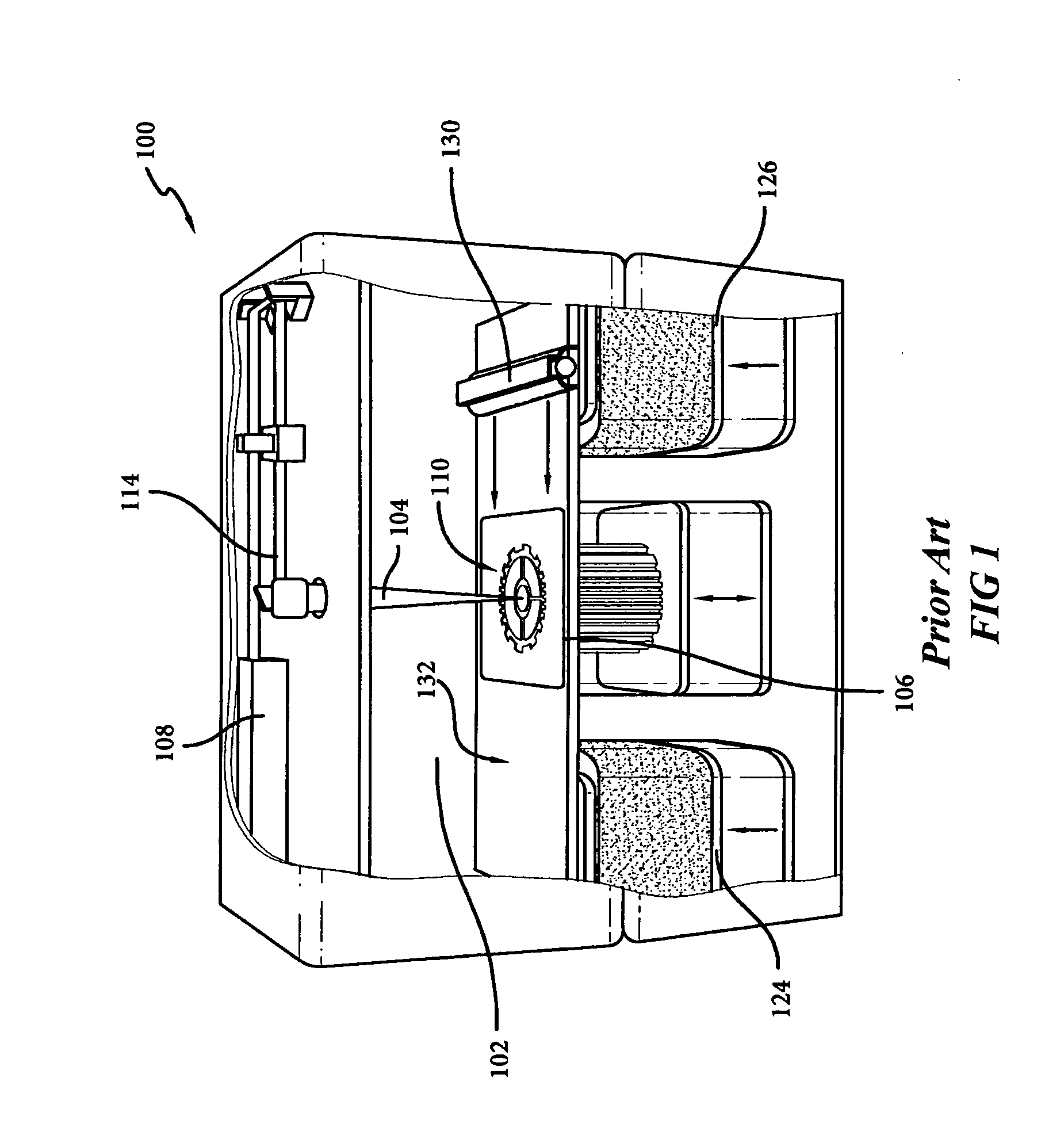
[0037]FIG. 1 illustrates, by way of background, a conventional laser sintering system, indicated generally as the numeral 100, currently sold by 3D Systems, Inc. of Valencia, Calif. FIG. 1 is a rendering shown without doors for clarity. A carbon dioxide laser 108 and its associated scanning system 114 is shown mounted in a unit above a process chamber 102 that includes a top layer of powder bed 132, two feed powder cartridges 124, 126, and a spreading roller 130. The process chamber 102 maintains the appropriate temperature and atmospheric composition (typically an inert atmosphere such as nitrogen) for the fabrication of the article.

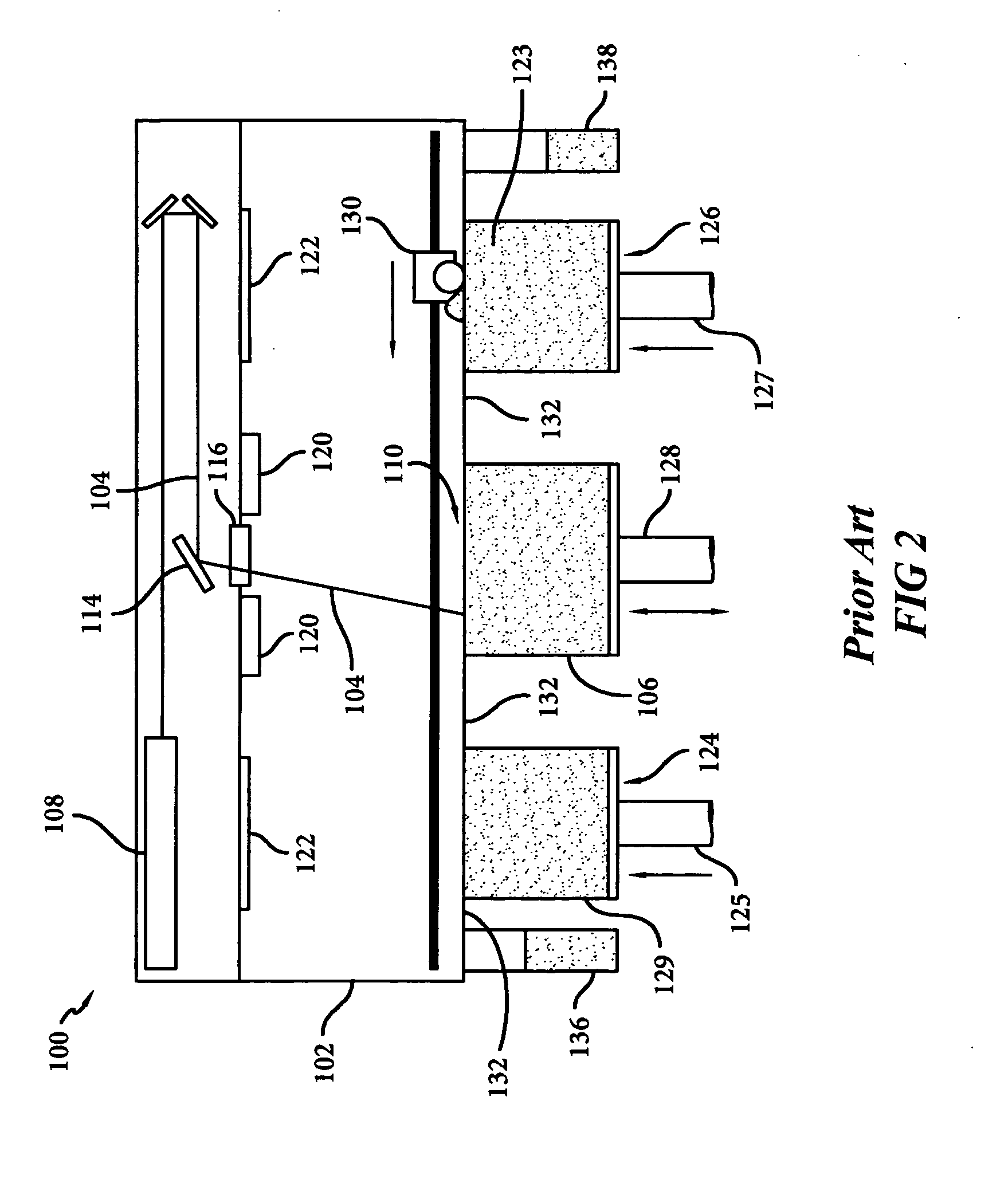
[0038] Operation of this conventional laser sintering system 100 is shown in FIG. 2 in a front view with the doors removed for clarity. A laser beam 104 is generated by laser 108, and aimed at target area 110 by way of optics-mirror scanning system 114, generally including galvanometer-driven mirrors that deflect the laser beam. The laser and galvanome...


PUM

PropertyMeasurementUnit
Pressureaaaaaaaaaa
Flow rateaaaaaaaaaa
Sizeaaaaaaaaaa

Abstract

A method and apparatus for forming three-dimensional objects by laser sintering that includes the use of dense phase pneumatic conveying to internally recycle overflow powder, and to thoroughly blend overflow, recovered and virgin powder to provide a consistent powder feed mix to a laser sintering machine. Overflow powder from the laser sintering machine is recovered and recycled back into the laser sintering machine for reuse. The approach results in a compact and reliable powder recycle system with complete blending and minimum attrition to the handled powder.

Description

BACKGROUND OF THE INVENTION [0001] This invention is in the field of freeform fabrication, and is more specifically directed to the fabrication of three-dimensional objects by selective laser sintering. [0002] The field of freeform fabrication of parts has, in recent years, made significant improvements in providing high strength, high density parts for use in the design and pilot production of many useful articles. Freeform fabrication generally refers to the manufacture of articles directly from computer-aided-design (CAD) databases in an automated fashion, rather than by conventional machining of prototype articles according to engineering drawings. As a result, the time required to produce prototype parts from engineering designs has been reduced from several weeks to a matter of a few hours. [0003] By way of background, an example of a freeform fabrication technology is the selective laser sintering process practiced in systems available from 3D Systems, Inc., in which articles...

Claims


Application Information

Patent Timeline
IPC IPC(8): B29C35/08
CPCB01F3/188B01F5/10B01F5/246B22F2003/1059B29C67/0077B33Y30/00B29B17/0005Y02W30/62B29C64/153B33Y40/00B29C64/357Y02P10/25B01F23/69B01F25/50B01F25/83B22F10/28B22F12/52B22F10/73B22F12/55B22F12/63B22F10/322Y02P10/20
Inventor COX, BRIAN DAVID
Owner 3D SYST INC
Why Eureka
Try Eureka