

Ferroelectric memory
a ferroelectric memory and capacitor technology, applied in the field of ferroelectric memory, can solve the problems of wasting electric power, limiting the number of read operations, and wasting electric power by repeating the reverse polarization in the read operation. achieve the effect of reliably reading data stored in the memory cell, accurate voltage change, and readily generating pre-charging voltag
- Summary
- Abstract
- Description
- Claims
- Application Information
AI Technical Summary
Benefits of technology
Problems solved by technology
Method used
Image

Examples
first embodiment
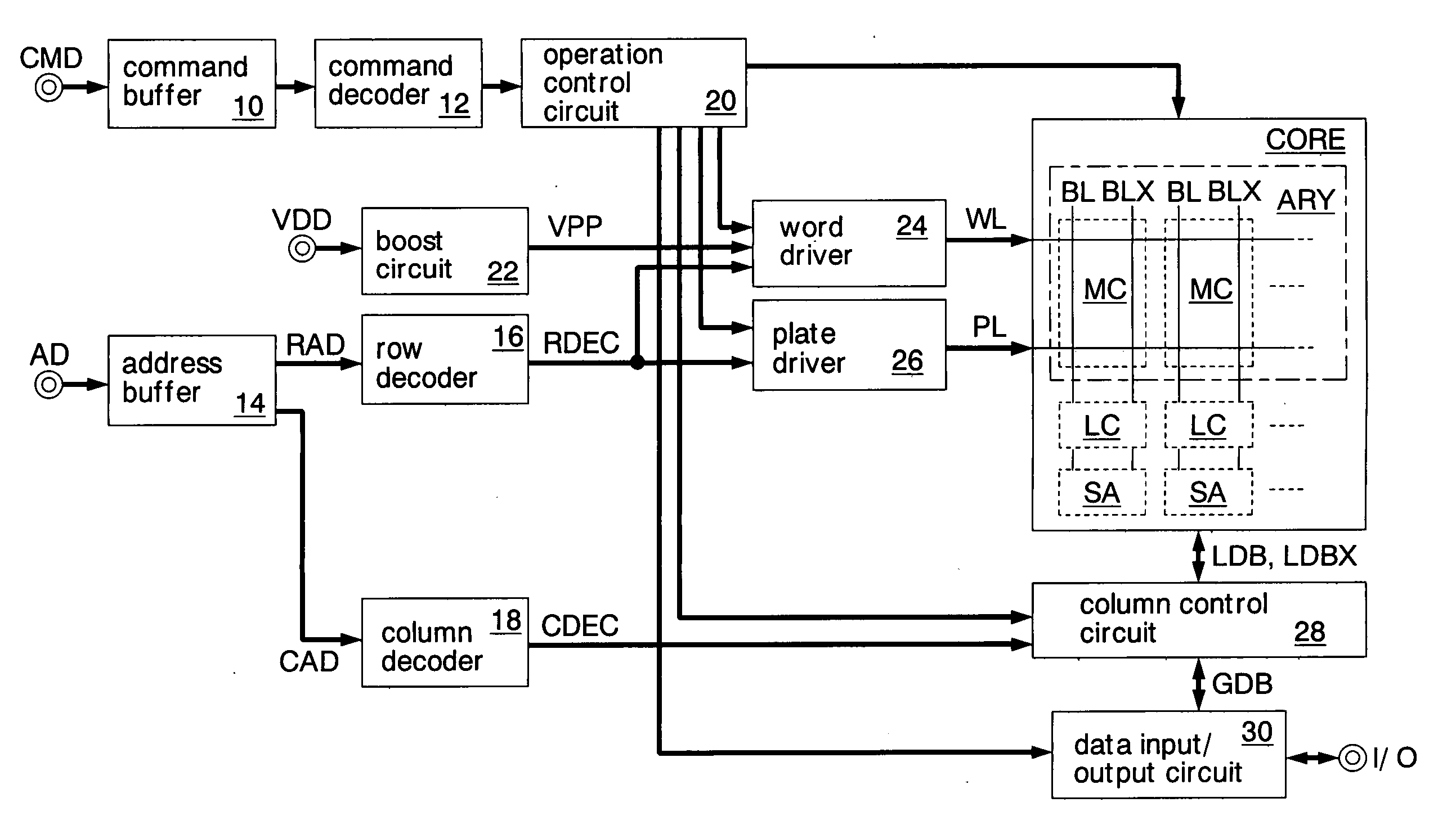
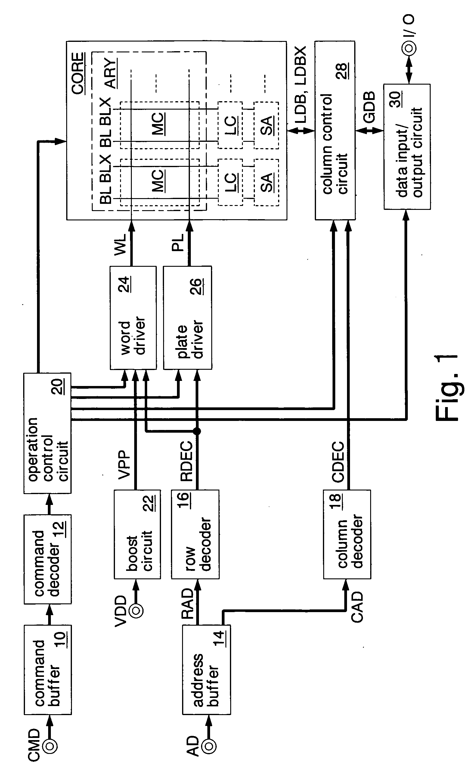
[0028]FIG. 1 shows a ferroelectric memory according to the invention. The ferroelectric memory is formed on a silicon substrate by use of a CMOS process. The ferroelectric memory is incorporated as a memory core in a system LSI mounted on, for instance, a mobile phone. When the ferroelectric memory is adopted, a plurality of kinds of memories (for instance, flash memory and DRAM) that is so far used in a mobile phone can be reduced to one kind.
[0029] The ferroelectric memory includes a command buffer 10, a command decoder 12, an address buffer 14, a row decoder 16, a column decoder 18, an operation control circuit 20, a voltage booster 22, a word driver 24, a plate driver 26, a memory core CORE, a column control circuit 28 and a data input / output circuit 30.
[0030] The command buffer 10 receives a command signal CMD such as a chip select signal, an output enable signal or a write enable signal through a command terminal CMD and outputs to the command decoder 12. The command decoder ...
third embodiment
[0074]FIG. 6 shows a read operation of a ferroelectric memory according to the Operations the same as that described in the FIG. 3 are omitted from detailing. In the embodiment, the pre-sense signal PSAEX is activated after the restore signal RSTRZ is activated and before a plate line PL changes to a high level. A timing when the pre-sense signal PSAEX is inactivated is the same as the restore signal RSTRZ. An activation level (high level voltage) of the restore signal RSTRZ is a power supply voltage VDD (2 V). Other operations are the same as FIG. 3.
[0075] The pMOS transistors P4 and P5 of the pre-sense amplifier PSA are activated responding to the activation of the pre-sense signal PSAEX (FIG. 6 (a)). In the example, the pMOS transistor P4 is turned on in response to a change of a bit line BLX corresponding to the local data bus line LDBX changed to a low level voltage VSS to a low level voltage VSS. When the pMOS transistor P4 is turned on, a voltage of the bit line BL assuredly...
fourth embodiment
[0080]FIG. 8 shows a read operation of a ferroelectric memory according to the Operations the same as that described in the FIG. 3 are omitted from detailing. The embodiment has a feature in a precharging operation of the bit lines BL and BLX before a read operation begins.
[0081] In the precharging operation, firstly, a precharging signal PRE1Z is activated for a predetermined period (FIG. 8 (a)) and the bit lines BL and BLX, respectively, change to a high level voltage (VDD—a threshold voltage of an nMOS transistor N8) and a ground voltage VSS. That is, the bit line BL is charged in accordance with a high level voltage (FIG. 8 (b)). After the precharging signal PRE1Z is inactivated, a precharging signal PRE2Z is activated for a predetermined period (FIG. 8 (c)). When the precharging signal PRE2Z is activated, the bit lines BL and BLX are equalized and set at a desired precharging voltage VPR (one half a voltage of the bit line BL) (FIG. 8 (d)). That is, the precharging voltage VPR...
PUM
 Abstract
Description
Claims
Application Information