
Quantum cascade laser with grating formed by a periodic variation in doping

a quantum cascade laser and periodic variation technology, applied in the direction of laser details, laser optical resonator construction, basic electric elements, etc., can solve the problems of high requirements for plasmon confinement in visible and near-infrared wavelengths, very lossy surface plasmons, and inability to coupling between the surface plasmon mode and the lasing mode,

Inactive Publication Date: 2006-09-28
AVAGO TECHNOLOGIED FIBER IP SINGAPORE PTE LTD
View PDF9 Cites 24 Cited by
  • Summary
  • Abstract
  • Description
  • Claims
  • Application Information

AI Technical Summary

Benefits of technology

[0006] Placement of doped diffraction gratings in the waveguide region of QCLs provides a distributed Bragg reflector (DBR) for stabilizing the emission wavelength. In accordance with the invention, doped diffraction gratings may also be used to provide a DBR for mid-IR wavelength VCSELs.

Problems solved by technology

Surface plasmons are very lossy and any coupling between the surface plasmon mode and the lasing mode is not desirable because this coupling creates an additional loss mechanism for the laser.
Plasmon-waveguide structures have been introduced for transverse-mode confinement in QCLs because of the impracticality of growing cladding layers sufficiently thick to contain the long evanescent tail of the transverse mode present at the longer emission wavelengths of intersubband semiconductor lasers such as QCLs.
The requirements for doping in the visible and near-infrared wavelengths for plasmon confinement are typically too high to be practicable.

Method used


Image

  • Quantum cascade laser with grating formed by a periodic variation in doping
  • Quantum cascade laser with grating formed by a periodic variation in doping
  • Quantum cascade laser with grating formed by a periodic variation in doping

Examples


Embodiment Construction

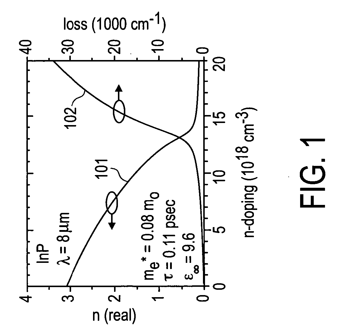
[0017] Heavy doping levels on the order of about 1018 / cm3 are sufficient to produce appreciable refractive index reductions in InP layers. In FIG. 1, plot 101 shows that for a QCL operating at 8 μ m with InP cladding layers, if the doping level is increased from 1-2×10¹⁷ / cm3 to 5×10¹⁸ / cm3 this corresponds to a reduction of real refractive index from about 3.1 to about 2.6. Plot 102 in FIG. 1 shows the increased loss as a function of the doping level.

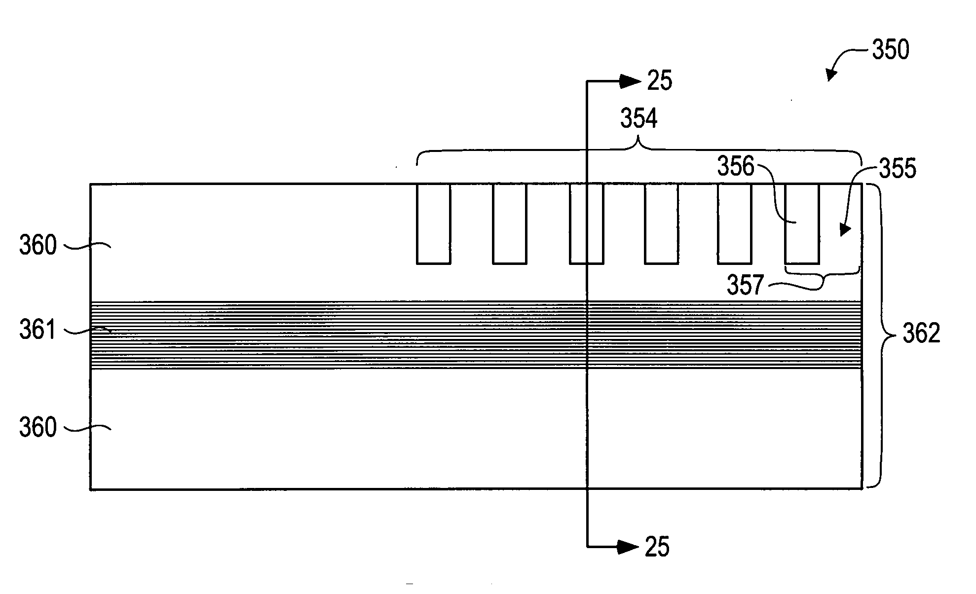
[0018] In accordance with the invention, a periodic variation of the doping can be used to produce a diffraction grating. The typical period for the doping variation, L, is given by L =λ / 2neff where neff is the effective refractive index and λ is the wavelength. A typical value for the period for the doping is on the order of 1 μ m. Alternatively, higher order gratings can be defined by using odd multiples of λ / 2neff (2m+1)λ / 2neff where m is a positive integer. If this diffraction grating is appropriately positioned in the waveguide reg...


PUM


Abstract

Doped diffraction gratings for use in quantum cascade lasers and mid-infrared wavelength vertical cavity surface emitting lasers can be made by introducing periodic variations in the doping levels that result in periodic refractive index variations. Doping is typically accomplished by use of an n type dopant.

Description

BACKGROUND [0001] Quantum cascade lasers (QCL) use electronic intersubband transitions for lasing action in semiconductor superlattices. For light to be either strongly emitted or absorbed by intersubband transitions, the electric field of the light is typically perpendicular to the epitaxial layers and transverse magnetic (TM) polarized light is predominantly absorbed or emitted by intersubband transitions in quantum wells. [0002] Surface plasmons are TM polarized waves that propagate along a metal and semiconductor interface. The amplitude of surface plasmons decreases exponentially on both sides of the interface. Surface plasmons are very lossy and any coupling between the surface plasmon mode and the lasing mode is not desirable because this coupling creates an additional loss mechanism for the laser. [0003] Plasmon-waveguide structures have been introduced for transverse-mode confinement in QCLs because of the impracticality of growing cladding layers sufficiently thick to cont...

Claims


Application Information

Patent Timeline
Patent Type & Authority Applications(United States)
IPC IPC(8): H01S3/30H01S5/00
CPCB82Y20/00H01S5/12H01S5/125H01S5/183H01S5/3027H01S5/305H01S5/3402H01S5/00H01S3/0941
Inventor CORZINE, SCOTT W.BOUR, DAVID P.HOFLER, GLORIA E.
Owner AVAGO TECHNOLOGIED FIBER IP SINGAPORE PTE LTD
Learn More