Tunable laser

a laser and tunable technology, applied in the field of tunable lasers, can solve the problems of high shelf control cost, difficult to tune the dfb-ld for a wide range, and the problem of dfb-ld-based wdm transmission system, etc., and achieve the effects of low cost, high reliability, and high performan

Inactive Publication Date: 2006-10-05
NEC CORP
View PDF8 Cites 38 Cited by
  • Summary
  • Abstract
  • Description
  • Claims
  • Application Information

AI Technical Summary

Benefits of technology

[0014] It is an object of the present invention to provide a tunable laser which will solve the problems of the conventional tunable lasers, is highly reliable, is of high performance and low cost, and has a simple arrangement for monitoring wavelengths.

Problems solved by technology

However, since it is impossible to tune the DFB-LD for a wide range of oscillation wavelengths, a DFB-LD-based WDM transmission system employs DFB-LD devices having different wavelengths for respective ITU (International Telecommunication Union) grids.
The need for using DFB-LD devices having different wavelengths makes the DFB-LD-based WDM transmission system problematic because the shelf control cost is high and a redundant inventory of DFB-LDs is required in preparation for DFB-LD failures.
If the ROADM system that is capable of optical path switching by changing wavelengths employs ordinary DFB-LDs, then the variable extent of the wavelength range is limited to about 3 nm that can be changed with a temperature change, making it difficult to construct an optical network incorporating the features of the ROADM that positively uses wavelength resources.
Though many structures have been proposed for use as conventional tunable lasers, it has been difficult to put them to practical use because of various problems including mode hopping, complex wavelength control, weak vibration resistance, and high cost due to device enlargement.
If crystal defects grow on account of the electric current injection, then the ratio of a refractive index change to the electric current injection changes greatly, making it difficult to maintain laser oscillation at a constant wavelength over a long period of time.
Consequently, it is difficult to reduce the present price of DBR-LDs.
The tunable lasers with the wavelength varying mechanism disposed in the laser element are liable to bring about mode jumping due to vibration.
These tunable lasers need a large vibration-resistant mechanism and tend to have a large module size and an increased cost.
The tunable lasers also suffer an increased assembling cost as they require many optical components such as a photodetector in addition to the etalon for monitoring oscillating wavelengths.
However, the highly accurate mounting technology is also responsible for an increase in the assembling cost of tunable lasers.

Method used


Image

  • Tunable laser
  • Tunable laser
  • Tunable laser

Examples


first embodiment

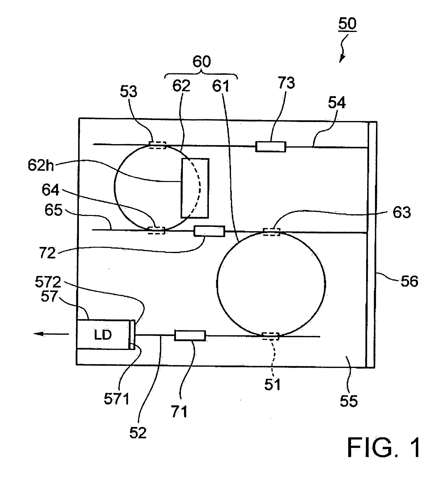
[0038] Tunable laser 50 according to the present invention, shown in FIG. 1, has PLC substrate 55 with multiple ring resonator 60, input / output side waveguide 52, and reflection side waveguide 54 being disposed thereon. Multiple ring resonator 60 comprises two ring resonators 61, 62 having respective ring-shaped waveguides and respective different optical path lengths. Ring resonators 61, 62 are coupled to each other by directional couplers 63, 64 and coupling waveguide 65 thereby constituting multiple ring resonator 50. Input / output side waveguide 52 has an end coupled to ring resonator 61 by directional coupler 51. Reflection side waveguide 54 has an end coupled to ring resonator 62 by directional coupler 53. The other end of reflection side waveguide 54 extends to an end of PLC substrate 55 on which highly reflecting film 56 is disposed as an optical reflector. Therefore, highly reflecting film 56 is disposed at the other end of reflection side waveguide 54. Highly reflecting fil...

second embodiment

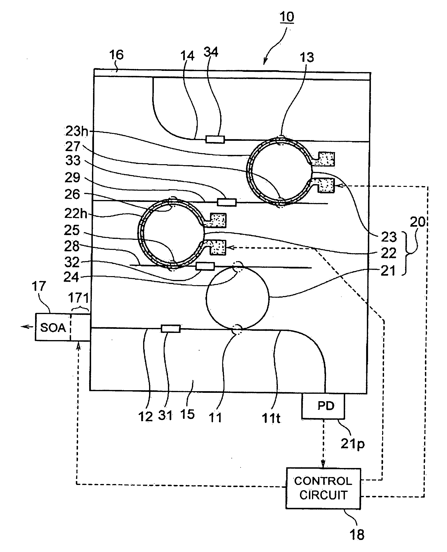
[0062] Operation principle of tunable laser 10 will be described below with reference to FIGS. 3 and 4.

[0063] Light emitted from SOA 17 enters from optical input / output end 172 into input / output side waveguide 12, and travels to highly reflecting film 16 successively through mode filter 31, directional coupler 11, multiple ring resonator 20 in which mode filters 32, 33 are inserted, directional coupler 13, and reflection side waveguide 14 in which mode filter 34 is inserted. The light is reflected by highly reflecting film 16, and travels back to optical input / output end 172 and hence SOA 17 successively through reflection side waveguide 14 in which mode filter 34 is disposed, directional coupler 13, multiple ring resonator 20 in which mode filters 32, 33 are disposed, directional coupler 11, input / output side waveguide 12 in which mode filter 31 is disposed. The returning light has been reflected by highly reflecting film 16 having a predetermined wavelength-dependency and has pas...


PUM


Abstract

A tunable laser has a multiple ring resonator comprising a plurality of ring resonators having respective ring-shaped waveguides and respective different optical path lengths, an input/output side optical waveguide coupled to the multiple ring resonator, an optical input/output device such as a laser diode coupled to the input/output side optical waveguide, a reflection side optical waveguide coupled to the multiple ring resonator, an optical reflector coupled to the reflection side optical waveguide for removing light at an unwanted wavelength and reflecting light at a required wavelength, and a wavelength varying mechanism for changing the resonant wavelength of the multiple ring resonator.

Description

BACKGROUND OF THE INVENTION [0001] 1. Field of the Invention [0002] The present invention relates to a tunable laser which can vary the oscillation wavelength thereof. [0003] 2. Description of the Related Art [0004] As broadband communications are becoming more and more popular, attempts are being made to introduce WDM (Wavelength Division Multiplexing) transmission systems that are capable of communications at a plurality of different optical wavelengths over a single optical fiber for efficient utilization of fiber optic transmission paths. Recently, DWDM (Dense WSD) apparatus for multiplexing optical signals of several tens of wavelengths for more rapid transmission have also been finding growing use. Efforts have also been made to commercialize ROADM (Reconfigurable Optical Add / Drop Multiplexers) for adding and dropping optical signals of desired wavelengths at each node in the optical networks. If ROADM systems are introduced into the communication environment, then the flexibi...

Claims


Application Information

Patent Timeline
Patent Type & Authority Applications(United States)
IPC IPC(8): H01S3/083G02B6/12H01S3/082H01S5/06H01S5/14
CPCH01S5/02248H01S5/02415H01S5/0612H01S5/142H01S5/0687H01S5/1032H01S5/0654H01S5/02325H01S3/10
Inventor YAMAZAKI, HIROYUKI
Owner NEC CORP
Why Eureka
Try Eureka