Semiconductor manufacture method
a manufacturing method and semiconductor technology, applied in semiconductor/solid-state device testing/measurement, semiconductor/solid-state device details, instruments, etc., can solve problems such as the possibility of erroneous detection, and achieve the effect of preventing local position misalignment, removing abnormal values of position information, and avoiding local position displacemen
- Summary
- Abstract
- Description
- Claims
- Application Information
AI Technical Summary
Benefits of technology
Problems solved by technology
Method used
Image
Examples
first embodiment
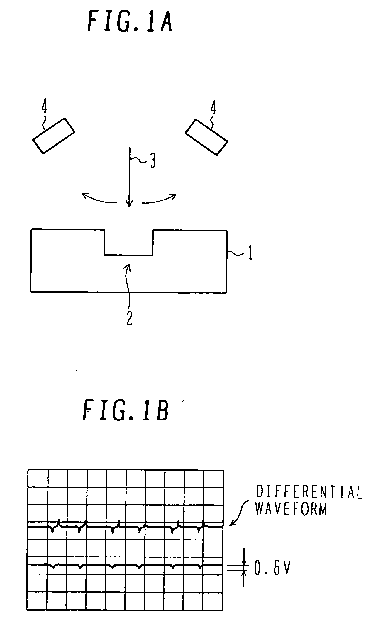
[0050] With reference to FIGS. 4A and 4B, EB exposure of the first embodiment will be described. The process shown in FIG. 3A is executed to form a resist pattern on a silicon substrate, the resist pattern having an opening for an element isolation groove pattern in a semiconductor integrated circuit device area and for an alignment mark pattern. By using the resist pattern as a mask, trenches are etched in the silicon substrate to form steps. Element isolation shallow trenches and alignment marks are formed at the same time. The step is usually about 0.3 μm although it changes depending upon semiconductor integrated circuit devices to be manufactured. An oxide film burying the trench is formed and an unnecessary oxide film is removed by a CMP process to form the structure shown in FIG. 3B. By executing several processes, an insulating film shown in FIG. 3C is formed before contact holes are formed. In order to obtain alignment signals, it is necessary to recover the steps. As descr...
second embodiment
[0062]FIG. 6A shows an example of the layout of alignment marks in a wafer. An alignment mark 9 is disposed near each of four corners of each chip 8 in the wafer.
[0063]FIG. 6B is an enlarged view of one chip area. Alignment marks 9 are disposed without superposing upon scribe lines 10. If inspection after scribing is not necessary, alignment marks may be disposed superposing upon the scribe lines. In FIG. 6A, four alignment marks are disposed near each side of a chip, excepting the outermost side. These marks are assigned to two adjacent chips.
[0064] Alignment mark detection, alignment and exposure are repeated in the group unit including the unit of chip, the unit of chip column and the like. In this case, mark widths W1, W2, W3, W4 of each chip or mark widths W1(i), W2(i), W3(i), W4(i) of each group once obtained are used to determine the reference mark width of, for example, Wref=AVERAGE (W1, W2, W3,W4) or Wref=AVERAGE Σ(W1(i), W2(i), W3(i), W4(i)). The allowable range R of ΔW=...
third embodiment
[0067] As shown in FIG. 7, an alignment mark at each position is constituted of a pair of an X-direction mark MX and a Y-direction mark MY. Namely, each alignment mark 9 shown in FIG. 6A is constituted of two marks MX and MY. The widths of the X- and Y-direction marks MX and MY are the same.
[0068] The pair of X- and Y-direction marks are disposed in an area considered having the same process condition, and the X- and Y-direction marks are scanned alternately. An abnormal value is judged from a difference Δ=Wx−Wy between the X-direction mark width Wx and the Y-direction mark width Wy.
[0069] For example, a design value of the mark width is set to 2 μm and an allowable difference is set to 0.10 μm. If the mark width detection results of marks 1, 2, . . . are Wx1=2.10 μm, Wy1=2.11 μm, Wx2=2.40 μm, Wy2=2.10 μm, . . . , an XY difference of the second mark is in excess of the allowable difference. It is judged that there is an erroneous detection, and these values are removed from the po...
PUM
 Abstract
Description
Claims
Application Information
 - R&D
- Intellectual Property
- Life Sciences
- Materials
- Tech Scout
- Unparalleled Data Quality
- Higher Quality Content
- 60% Fewer Hallucinations
Browse by: Latest US Patents, China's latest patents, Technical Efficacy Thesaurus, Application Domain, Technology Topic, Popular Technical Reports.
© 2025 PatSnap. All rights reserved.Legal|Privacy policy|Modern Slavery Act Transparency Statement|Sitemap|About US| Contact US: help@patsnap.com


