Ultracryostat and frigidity supplying apparatus

a technology of supplying apparatus and insulating chamber, which is applied in the direction of indirect heat exchangers, domestic cooling devices, lighting and heating devices, etc., can solve the problems of large structural distortion, insufficient heat shields, and insufficient signal to noise ratios, so as to avoid heat flow back

Inactive Publication Date: 2006-10-12
YOKOGAWA ELECTRIC CORP
View PDF0 Cites 21 Cited by
  • Summary
  • Abstract
  • Description
  • Claims
  • Application Information

AI Technical Summary

Benefits of technology

[0013] In view of the foregoing, the object of the present invention is to provide a means to avoid heat flowback when a freezer is not in operation for a cryostat connected with a freezer for biomagnetic measurement, so as to solve the problem when a freezer is not in operation.

Problems solved by technology

However, a common problem in the ultracryostat described in description of related art, i.e. a cryostat for biomagnetism measurement is that sufficient heat shield cannot be obtained because vacuum heat insulation layer is structurally thin.
This problem is caused by a purpose of measurement.
That is, sufficient SN (a ratio of signal to noise) cannot be obtained unless a measurement is performed in a condition that a sensor under ultra low temperature is placed as close as possible to a feeble magnetic signal source.
When volume of the cryostat is made larger, structural distortion becomes large and the thin vacuum heat insulation layer may brake to cause a thermal short.
Therefore, it cannot be made larger blindly.
However, it has not been into practical use due to the following problems regarding magnetic noise.
In view of the foregoing, it is difficult to attach a cryocooler directly onto a cryostat in a field of biomagnetic measurement.
However, because of large magnetic noise derived from a freezer, it is difficult to use any of the above devices for measurement when the freezer is in operation.
Further, when the freezer is not in operation during a measurement, heat flows back immediately.
Thus, noise increases in SQUID due to instability of the internal temperature as well as evaporation rate of helium extremely increases.

Method used


Image

  • Ultracryostat and frigidity supplying apparatus
  • Ultracryostat and frigidity supplying apparatus
  • Ultracryostat and frigidity supplying apparatus

Examples


embodiment 1

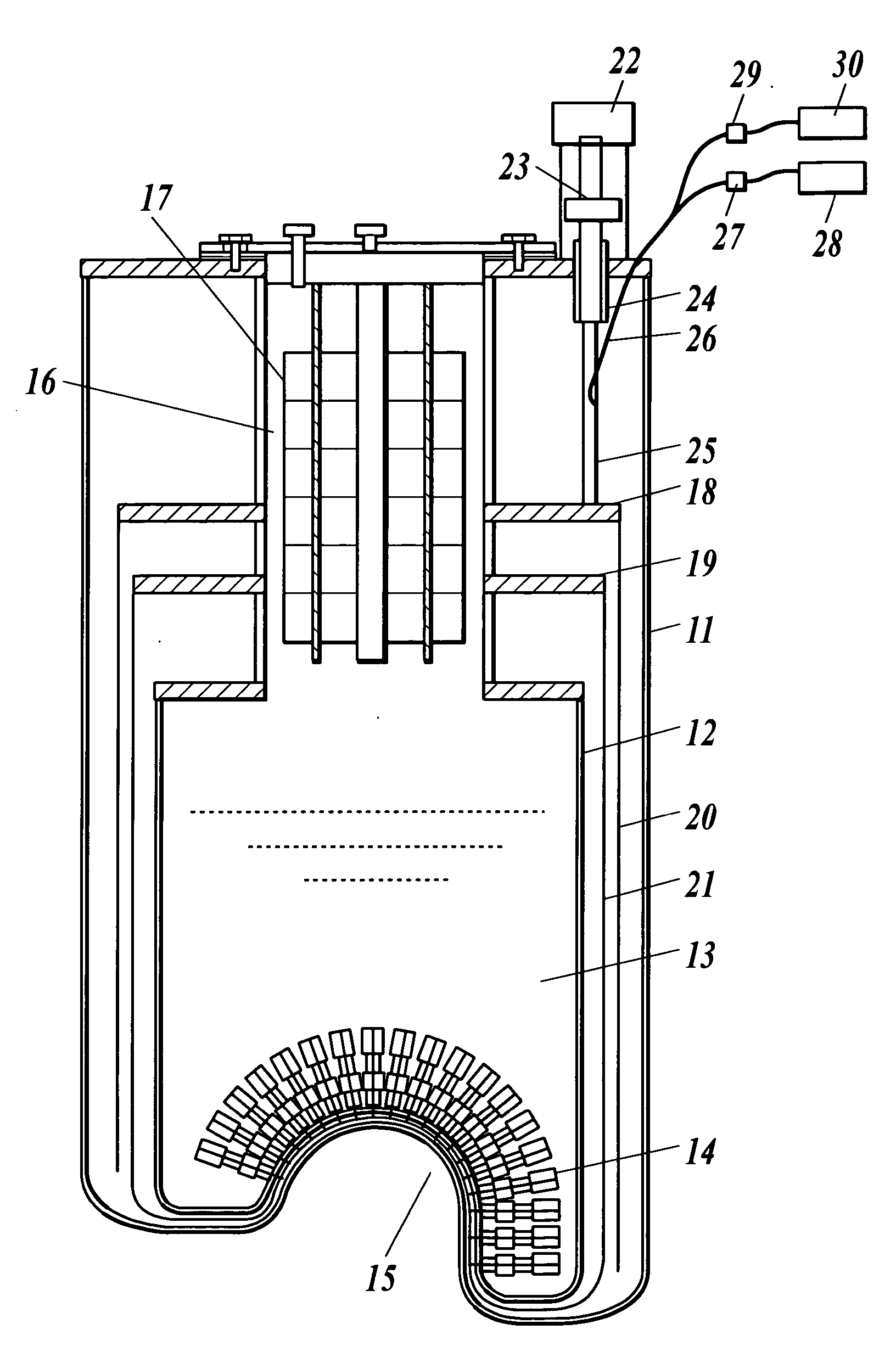
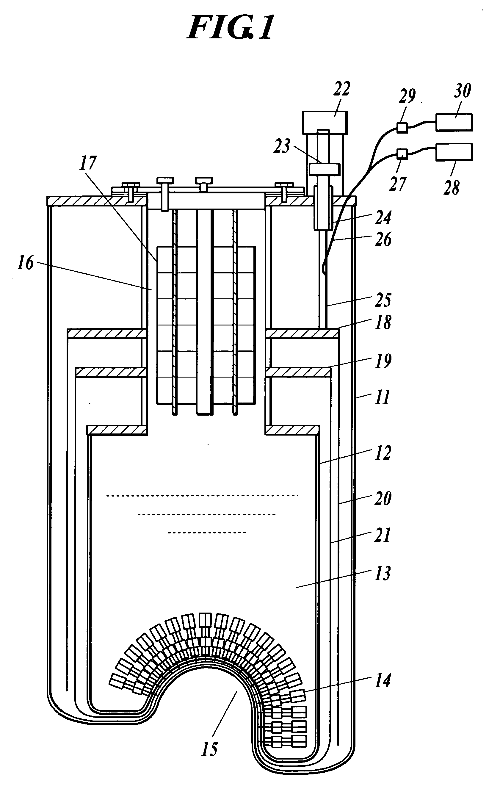
[0034] The feature of the invention is that the heat pipe having thermally variable conductance, i.e. having variable thermal conductivity, connects the cryocooler as the frigidity generating member with the thermal anchor continued to the radiation shield of the cryostat which requires the frigidity.

[0035] That is, by using the heat pipe which can switch frigidity transporting effect, frigidity conducts from the cryocooler to the thermal anchor when the cryocooler is ON, and heat does not conduct from the cryocooler to the thermal anchor when the cryocooler is OFF.

[0036] Here, for the following explanation, the frigidity designates an absorption of heat and has opposite meaning of heat diffusion or heat flow. Further, a high pressure supplying pipe and gas compressor and the like included in the cryocooler are omitted.

[0037]FIG. 1 is a whole constitution of the ultracryostat of the invention, and shows an embodiment in which the cryocooler is connected to the cryostat through th...


PUM


Abstract

A ultracryostat is provided with a frigidity supplying member to supply frigidity to the ultracryostat which uses cryogen such as liquid helium, wherein the frigidity supplying member comprises a heat pipe and one end of the heat pipe is connected to a frigidity generating member of a cryocooler and the other end of the heat pipe is connected to a thermal anchor of a cryostat.

Description

BACKGROUND OF THE INVENTION [0001] 1. Field of the Invention [0002] The present invention relates to an apparatus for extending low temperature retention time of a cryostat using a superconducting quantum interference device (SQUID) for biomagnetism measurement. In more detail, the present invention relates to an ultracryostat and a frigidity supplying apparatus to reduce evaporation of helium. Further, the present invention relates to an ultracryostat and a frigidity supplying apparatus applicable not only to an ultracryostat for biomagnetism measurement but also to the other cryostat, for example a helium cryostat for MRI (magnetic resonance imaging system) using superconductive magnet and one used in physicality study. [0003] 2. Description of Related Art [0004] As shown in FIG. 2, an ultracryostat in earlier development is such that a freezer 106 is connected to an upper part of an cryostat 105 installed in a magnetic shield room 104 (for example, JP Tokukai 2004-116914A (page 4...

Claims


Application Information

Patent Timeline
Patent Type & Authority Applications(United States)
IPC IPC(8): F25B9/00F25B19/00F25B9/14F25B23/00F25B25/00F25D19/00F25D29/00F28D15/02
CPCF25B9/14F25B23/006F25D29/001F25B2500/12F25D19/006F25B25/005
Inventor KAZAMI, KUNIO
Owner YOKOGAWA ELECTRIC CORP
Why Eureka
Try Eureka