

Tomographic imaging system using a conformable mirror
a technology of conformable mirrors and tomography, which is applied in tomography, instruments, and reconstructed two-dimensional cross sections. it can solve the problems of difficult interpretation of images, claustrophobic patients and children in the closed chamber of ct scan equipment, and affecting the quality of reconstructed two-dimensional cross sections
- Summary
- Abstract
- Description
- Claims
- Application Information
AI Technical Summary
Benefits of technology
Problems solved by technology
Method used
Image

Examples
first embodiment
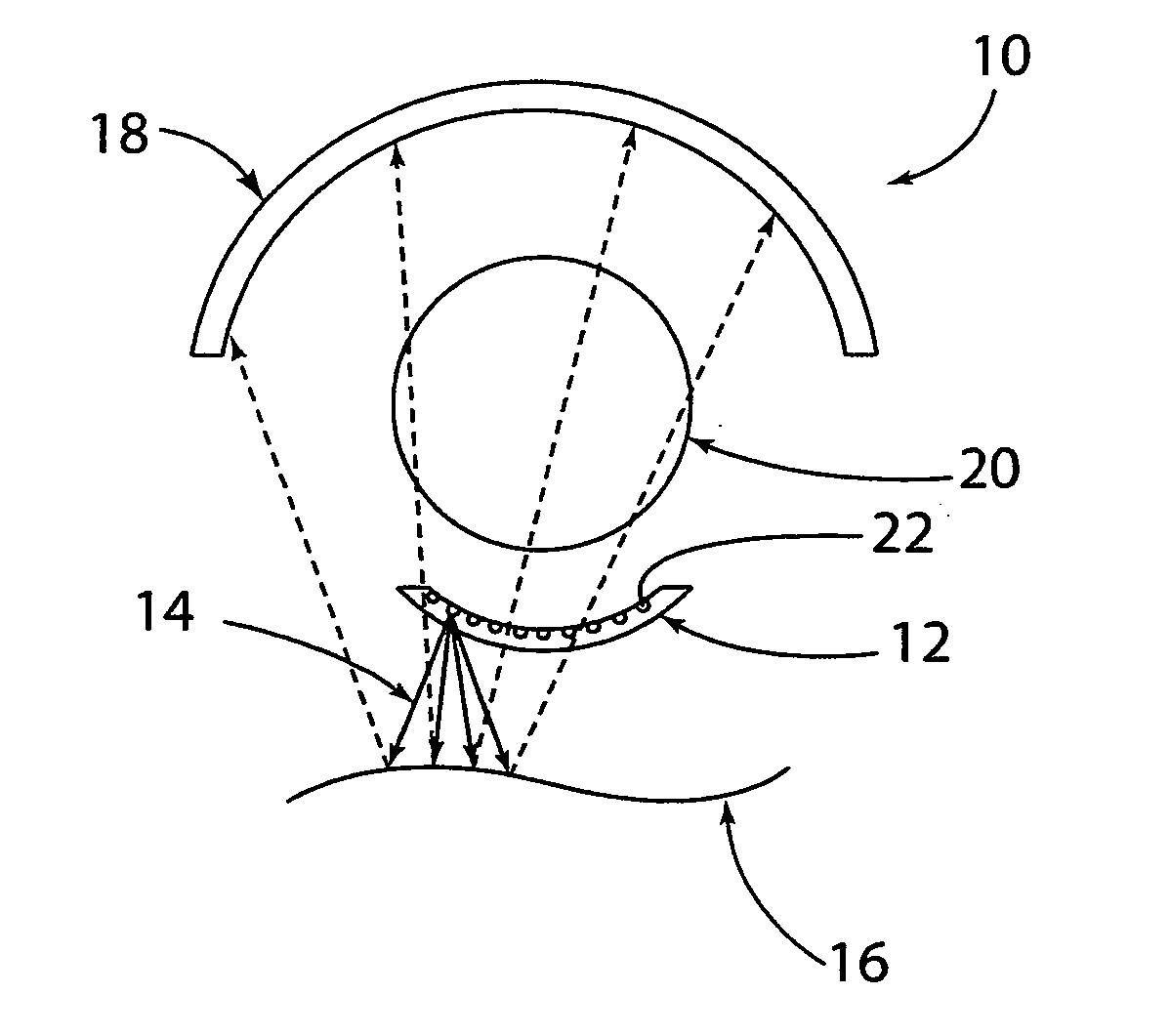
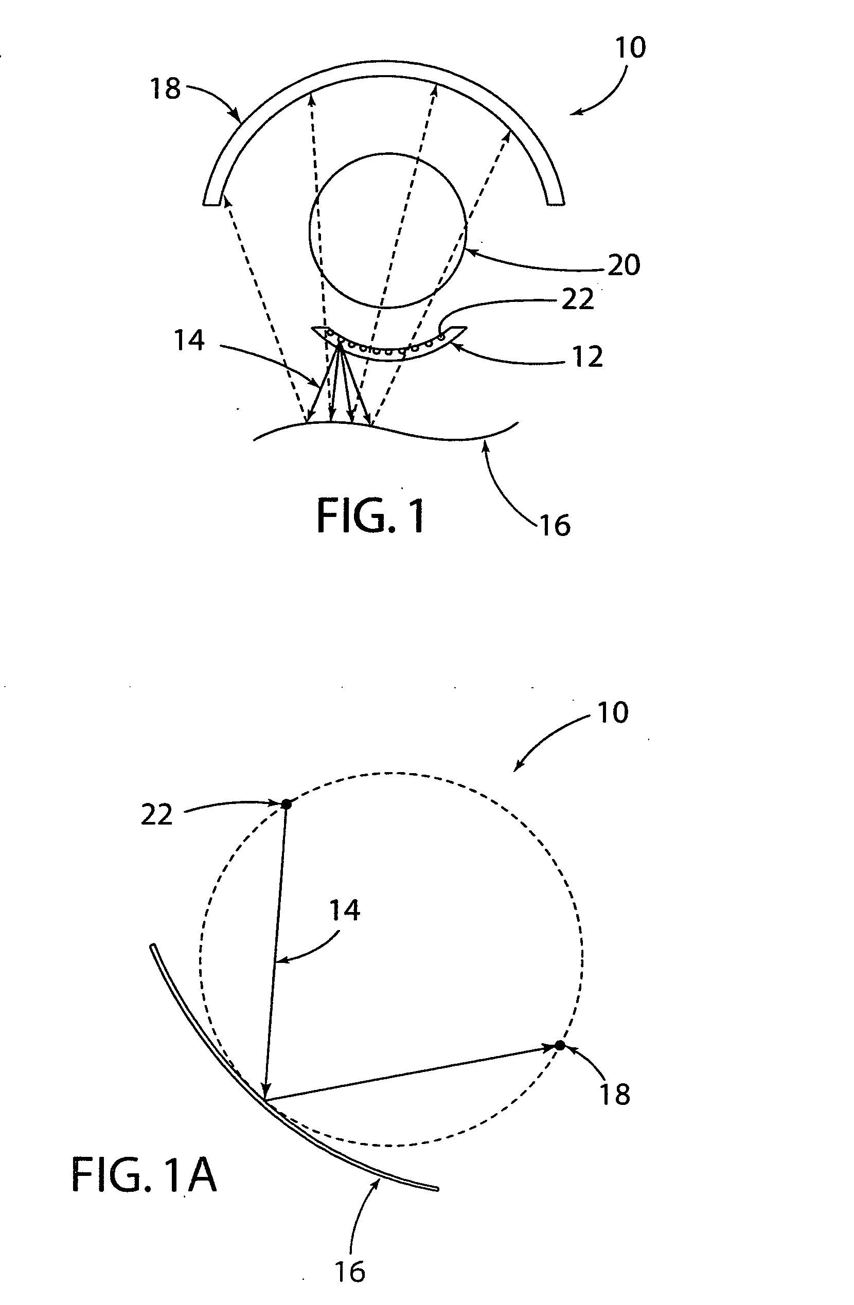
[0046]FIG. 1 illustrates a schematic diagram of the tomographic imaging system 10 of the present invention for a MMDM based X-ray CT technique for biomedical imaging. The illustrated system comprises a fan beam source array 12 and the detector array 18 both on an annular ring about the object's (e.g., a patient's) isocenter in a transverse imaging plane. The deformable mirror 16 is a continuous-membrane deformable X-ray reflecting mirror placed in the imaging plane on the same side as the source array 12. The configuration of the system 10 has limited field-of-view (LFOV) as the X-ray source array 12 is moved to few predetermined locations during projection measurement. In this quasi-stationary scan arrangement, the detector array 18 and the flexible deformable mirror 16 remain stationary.
[0047] During data collection, for each fan beam source position (i.e., position of the ray emitters 22 of the source array 12), projection data is collected for different unique mirror deflections...
second embodiment
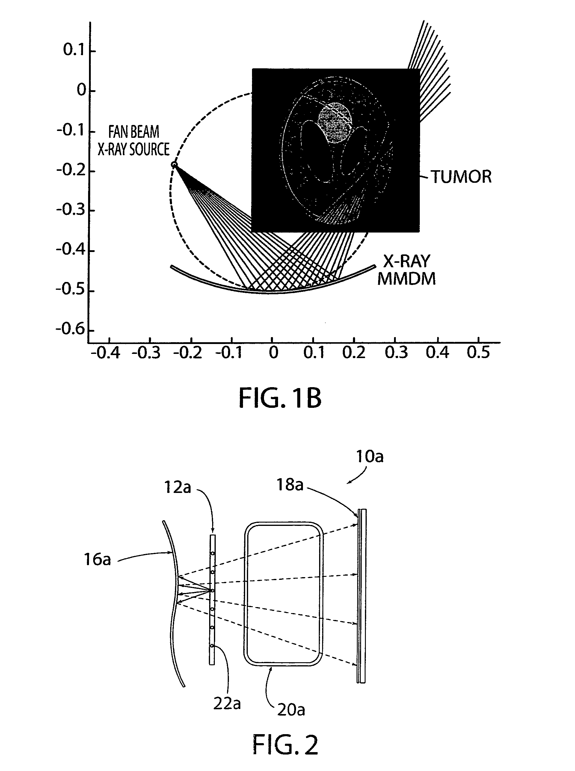
[0063] The reference numeral 10a (FIG. 2) generally designates another embodiment of the present invention, having a second embodiment for the system. Since system 10a is similar to the previously described system 10, similar parts appearing in FIG. 1 and FIG. 2, respectively, are represented by the same, corresponding reference number, except for the suffix “a” in the numerals of the latter. FIG. 2 shows the schematic diagram of the cross-sectional view of the proposed MMDM based X-ray CT system 10a for cargo container screening. The system 10 comprises a fan beam source array 12a and a linear detector array 18a positioned on either side of the cargo container 20a. The continuous-membrane deformable X-ray reflecting mirror 16a is placed on the same side as the source array 12. In this CT scan configuration, the detector array 18a and the X-ray reflective MMDM 16a device remain fixed and the fan beam X-ray source array 12a is moved to few predetermined locations for projection measu...
fifth embodiment
[0086]FIG. 19 generally designates another embodiment of the present invention, having a fifth embodiment for the system. The system 10c of FIG. 19 is preferably used for treating breast cancer. In the United States, breast cancer is the second leading cause of cancer deaths amongst women and it is anticipated that one in every eight American women will succumb to breast cancer before the age of 90. In recent years, hyperthermia and ablation have been suggested as an alternate adjuvant therapy to radiation and chemotherapy treatment of breast cancer. Clinical prototypes developed for radio frequency hyperthermia often employ a phased array or multiple antenna arrangement to elevate the temperature at the tumor site for selective tissue heating. FIG. 19 illustrates an alternative mode of hyperthermia / ablation treatment using a deformable membrane mirror 16c. The deformable mirror 16c with a reflective coating functions as an adaptive focusing mirror and delivers preferential energy d...
PUM
 Abstract
Description
Claims
Application Information