
Regenerable method and system for desulfurizing reformate

a reformate and regenerable technology, applied in the field of hydrogen-based reforming, can solve the problems of difficult to consistently deliver fuels with a sulfur level less than 30 ppm, fuel cell stacks can be particularly sensitive to sulfur, and sulfur is present, so as to reduce the amount of free oxygen and improve the regeneration effect of reformers

Active Publication Date: 2006-10-26
APTIV TECH LTD
View PDF6 Cites 21 Cited by
  • Summary
  • Abstract
  • Description
  • Claims
  • Application Information

AI Technical Summary

Benefits of technology

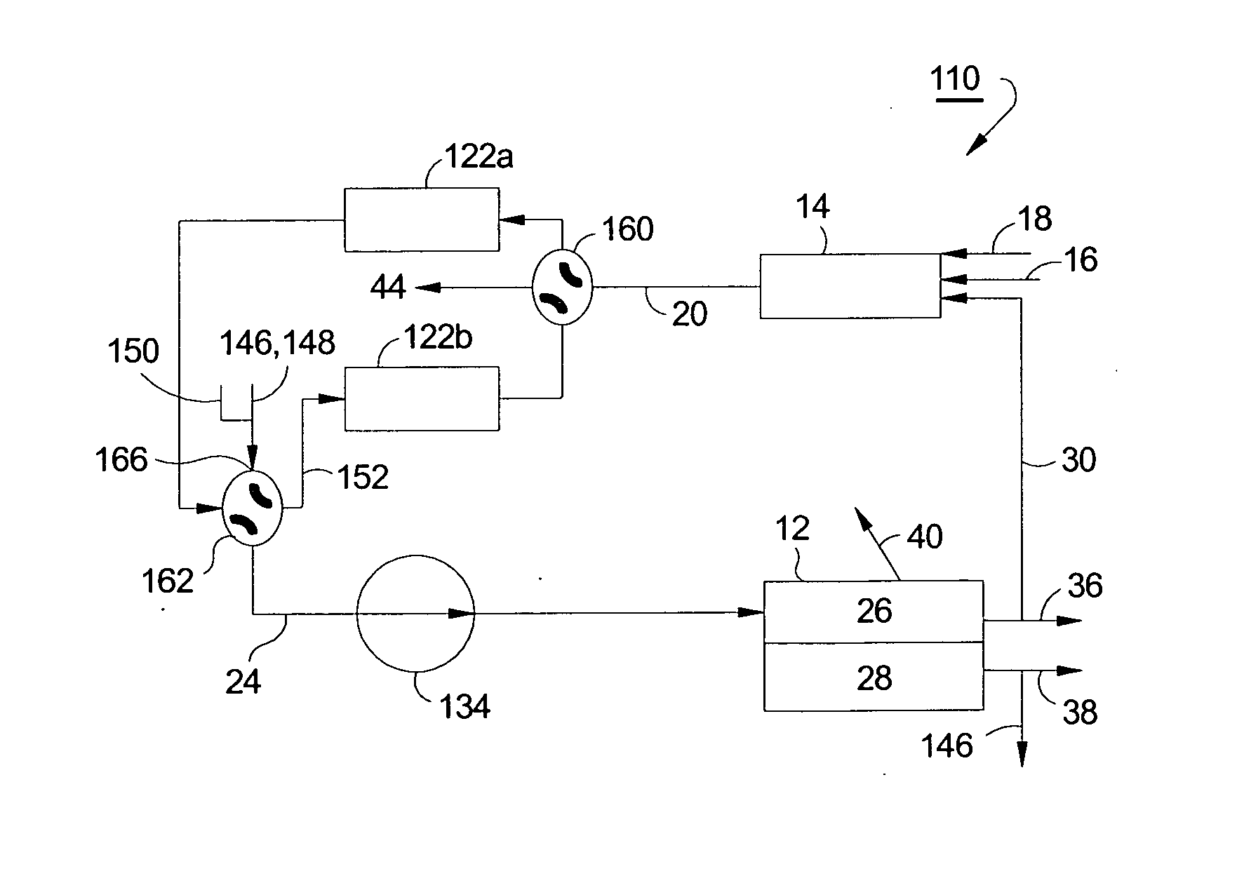
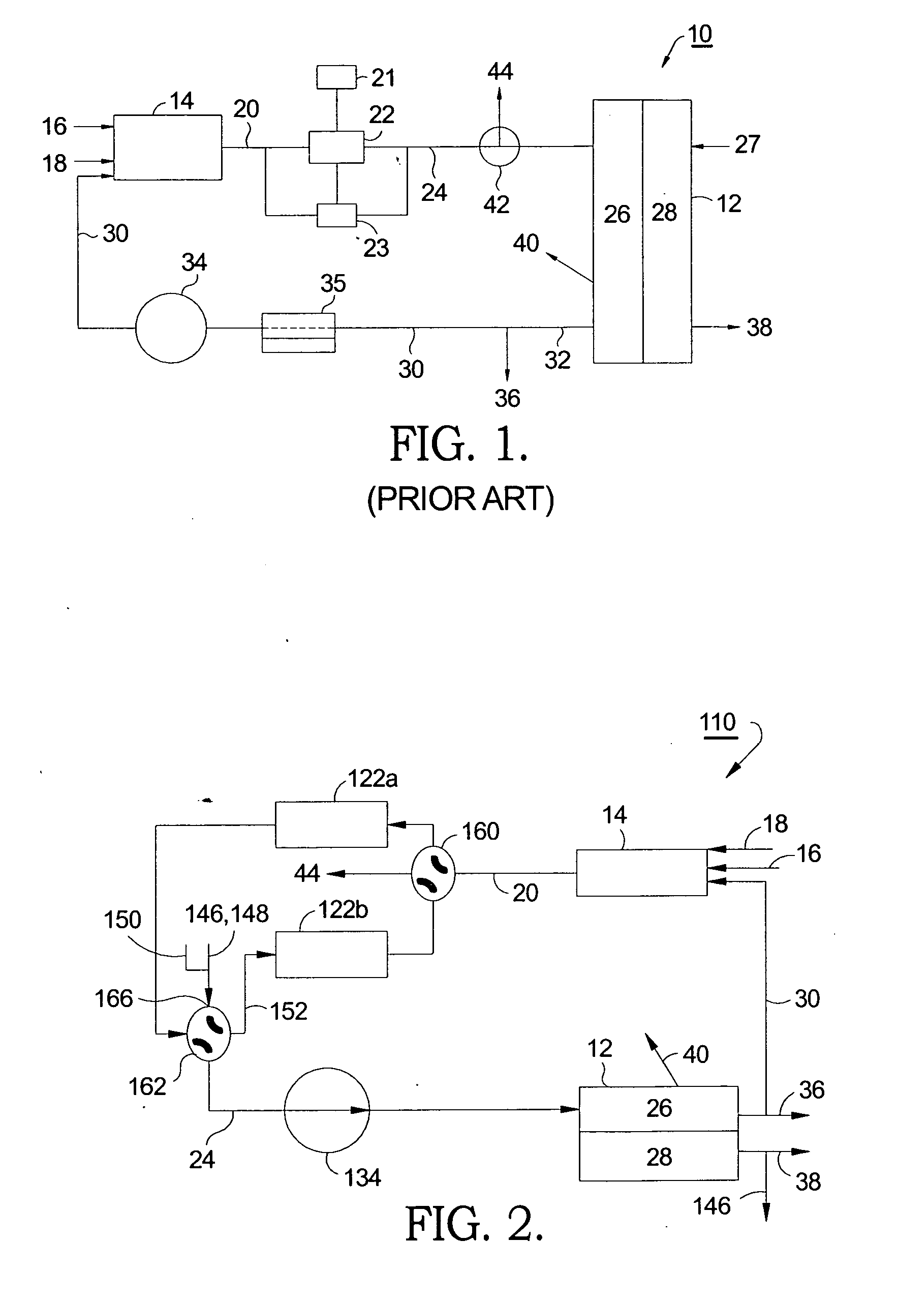
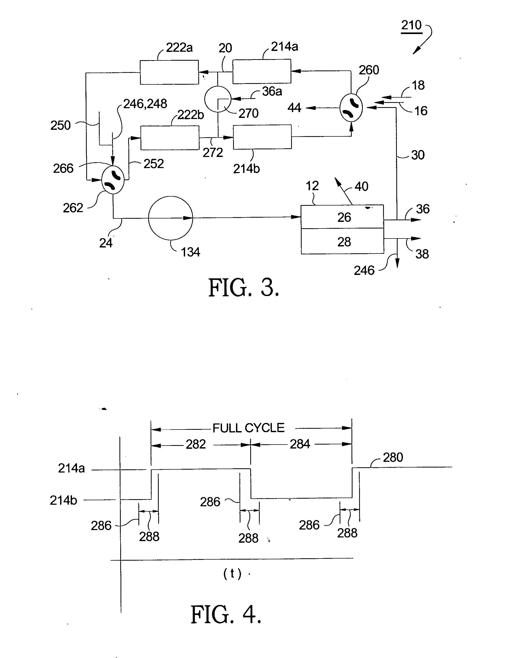
[0011] Briefly described, a system for removing sulfur from a continuous reformate stream comprises first and second regenerable sulfur traps disposed in parallel between a hydrocarbon reformer and a fuel cell assembly. The ends of the sulfur traps are connected to conventional four-way valves such that either trap may be selected for trapping sulfur from the reformate stream, while the other trap is undergoing regeneration by purging out the accumulated sulfur deposits. Thus, the sulfur traps may be loaded and purged alternately, permitting continuous supply of reformate to the fuel cell assembly. In a currently preferred embodiment, selected amounts of hot cathode air exhaust, hot anode gas exhaust and / or steam are used to control the temperature and oxygen concentration in the out-of-service trap, in order to assist in purging and thus regenerating the out-of-service trap. The timing of the adsorption / regeneration modes may be controlled so that regeneration occurs faster than adsorption to assure complete purging of sulfur before the trap is returned to its adsorption mode. In an alternate embodiment, a second reformer is disposed parallel to the first reformer and in series with the second regenerable sulfur trap so that the reformers may also be sequentially regenerated along with the associated sulfur traps. In a preferred embodiment, additional amounts of anode exhaust from the stack may be added to the stream between the regenerating trap and regenerating reformer to further reduce the amount of free oxygen flowing to the reformer to improve reformer regeneration. Alternatively, the amount of cathode exhaust flowing to the regenerating reformer from the regenerating sulfur trap may be reduced or completely switched off to control the temperature of and the oxygen concentration in the regenerating reformer.

Problems solved by technology

A serious problem in the use of such fuels can be the presence of sulfur and sulfurous compounds.
Some refinery streams and, for example, Fischer Tropsch synthetic diesel fuel are essentially sulfur-free—but when distributed in the fuel infrastructure it is very difficult to consistently deliver fuels with a sulfur level of less than 30 ppm.
Fuel cell stacks can be particularly sensitive to sulfur—which tends to accumulate in the anode and cut power density and efficiency.
In addition, endothermic reformer catalysts operating at low temperature tend to be particularly intolerant to sulfur, which can also adversely affect achievable reformer efficiency.
If coking or sooting occurs, due to a premature gas phase reaction before the fuel enters the reformer, within the reformer or as a post reaction in the system manifolding, the resulting particulate matter can enter the SOFC and degrade its efficiency and performance.
Thus the long term successful operation of the fuel cell system is compromised by sulfur in the fuel.
A drawback of the disclosed trappng system is that when the trap becomes loaded with trapped material, fuel cell operation must be suspended in order for the trap to be purged of the trapped material and thus regenerated.
A problem with this approach is that the fuel being reformed during regeneration is still contaminated with sulfur.
Another problem is that the temperature at the reformer exit may be more than 900 C during start-up which can deteriorate the active materials in the sulfur trap.
Yet another problem is that an extra heat exchanger must be used upstream of the reformer to cool recycled anode gas when the recycled gas is used to provide an oxidant for endothermic reforming.

Method used


Image

  • Regenerable method and system for desulfurizing reformate
  • Regenerable method and system for desulfurizing reformate
  • Regenerable method and system for desulfurizing reformate

Examples


Embodiment Construction

[0017] Referring to FIG. 1, a prior art system 10 includes a fuel cell stack 12, preferably a solid oxide fuel cell (SOFC) stack as is known in the art, although an apparatus in accordance with the invention is also useful for use with other types of fuel cell systems, for example, a molten carbonate fuel cell (MCFC) (not shown). A catalytic hydrocarbon reformer 14 receives a hydrocarbon fuel 16 and optionally air 18 and expels a reformate stream 20. Fuel 16 is preferably selected from the group consisting of, but not limited to, conventional liquid fuels, such as gasoline, diesel, ethanol, methanol, kerosene, and others; conventional gaseous fuels, such as natural gas, propane, butane, and others; and alternative fuels, such as hydrogen, biofuels, dimethyl ether, and others; and synthetic fuels, such as synthetic fuels produced from methane, methanol, coal gasification or natural gas conversion to liquids, combinations comprising at least one of the foregoing methods, and the like;...


PUM

PropertyMeasurementUnit
Flow rateaaaaaaaaaa
Heataaaaaaaaaa
Combustionaaaaaaaaaa

Abstract

A system for removing sulfur from a continuous reformate stream feeding a fuel cell stack. First and second sulfur traps are disposed in parallel between a hydrocarbon reformer and the fuel cell stack. The ends of the sulfur traps are connected to conventional four-way valves such that either trap may be selected for trapping sulfur from the reformate stream, while the other trap is undergoing regeneration by backflushing the accumulated adsorbed sulfur deposits. Thus, the sulfur traps may be used and stripped alternately, permitting continuous supply of desulfurized reformate to the fuel cell assembly. In a currently preferred embodiment, the hot cathode air exhaust is used to assist in stripping the out-of-service trap. In an alternative embodiment, two reformers are provided and the reformers are alternately regenerated along with their respective traps.

Description

[0001] This invention was made with United States Government support under Government Contract / Purchase Order and related contract nos. DMD19-01-2-0010 and GPA A006190.TECHNICAL FIELD [0002] The present invention relates to hydrocarbon reforming for supplying hydrogen-containing reformate fuels to fuel cells; more particularly, a system for removing sulfur from a reformate fuel stream; and most particularly, to an improved arrangement for continuously desulfurizing a reformate fuel stream. BACKGROUND OF THE INVENTION [0003] Fuel cells for combining hydrogen and oxygen to produce electricity are well known. A well known class of fuel cells, referred to in the art as “solid-oxidefuel cells (“SOFC”), includes a solid-oxide electrolyte layer through which oxygen anions migrate from a cathode to combine with hydrogen, forming water at the anode. In an SOFC, electrons flow through an external circuit between the electrodes, doing electrical work in a load in the circuit. [0004] In the p...

Claims


Application Information

Patent Timeline
IPC IPC(8): H01M8/06B01J8/04
CPCB01J2219/00006Y02E60/50C01B3/38C01B3/56C01B2203/0227C01B2203/0244C01B2203/0261C01B2203/043C01B2203/0485C01B2203/066C01B2203/142C01B2203/145C01B2203/146C01B2203/148H01M8/04089H01M8/0618H01M8/0675B01J2219/00038
Inventor GRIEVE, MALCOLM JAMESWEISSMAN, JEFFREY G.
Owner APTIV TECH LTD
Learn More