Geothermal system utilizing supplemental ground heat from drainage fields

a geothermal system and drainage field technology, applied in the field of geothermal system utilizing supplemental ground heat from drainage fields, can solve the problems of rapid reduction of heat recovery efficiency of these systems, rapid drop in heat recovery of heat recovered by these systems, and reducing the heat transfer coefficient between the wastewater, so as to increase the heat conductivity of the soil, increase the efficiency of geothermal system, and increase the rate of heat recovery

Inactive Publication Date: 2006-11-02
SPADAFORA PAUL F +2
View PDF0 Cites 27 Cited by
  • Summary
  • Abstract
  • Description
  • Claims
  • Application Information

AI Technical Summary

Benefits of technology

[0011] The liquid discharged from septic tanks is typically 5-10 degrees Fahrenheit higher than normal ground temperatures. Since the liquid distributed by the septic systems perforated pipes is subject to further exothermal bacterial digestion in the drain field, the ground temperatures under the drain fields will be effected not only by natural geothermal heat flux, but additional heating is achieved from the sensible heat from the waste liquids from the building and from the heat produced by the bacterial digestion in the septic tank and the drainage fields. Since higher moisture...

Problems solved by technology

In practice, the heat transfer efficiency of these systems rapidly decreases because wastewater is inherently dirty and causes a buildup of material on the heat exchange surfaces.
This fouling of the heat exchange surfaces reduces the heat transfer coefficient between the wastewater and the circulating fluid inside the coils and the amount of heat recovered by these systems drops off very quickly and renders them as being impractical.
However in actual practice, during the coldest periods of the year, the heat load obviously increases and the heat removal requirement from the ground in contact with ...

Method used


Image

  • Geothermal system utilizing supplemental ground heat from drainage fields
  • Geothermal system utilizing supplemental ground heat from drainage fields
  • Geothermal system utilizing supplemental ground heat from drainage fields

Examples


Embodiment Construction

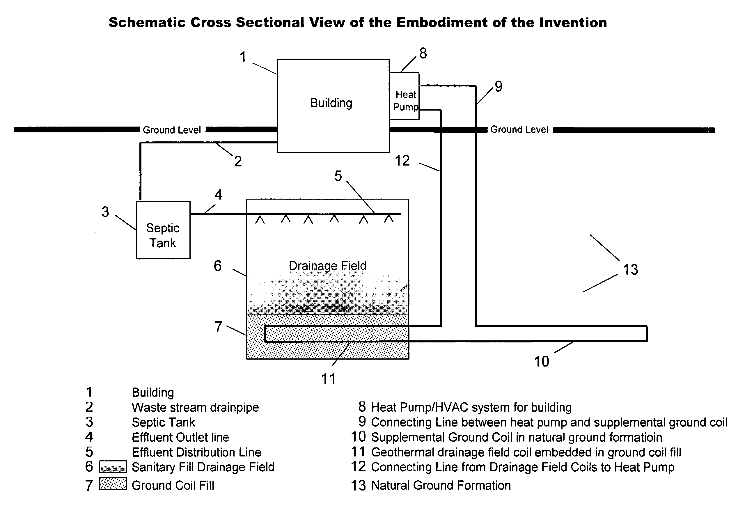
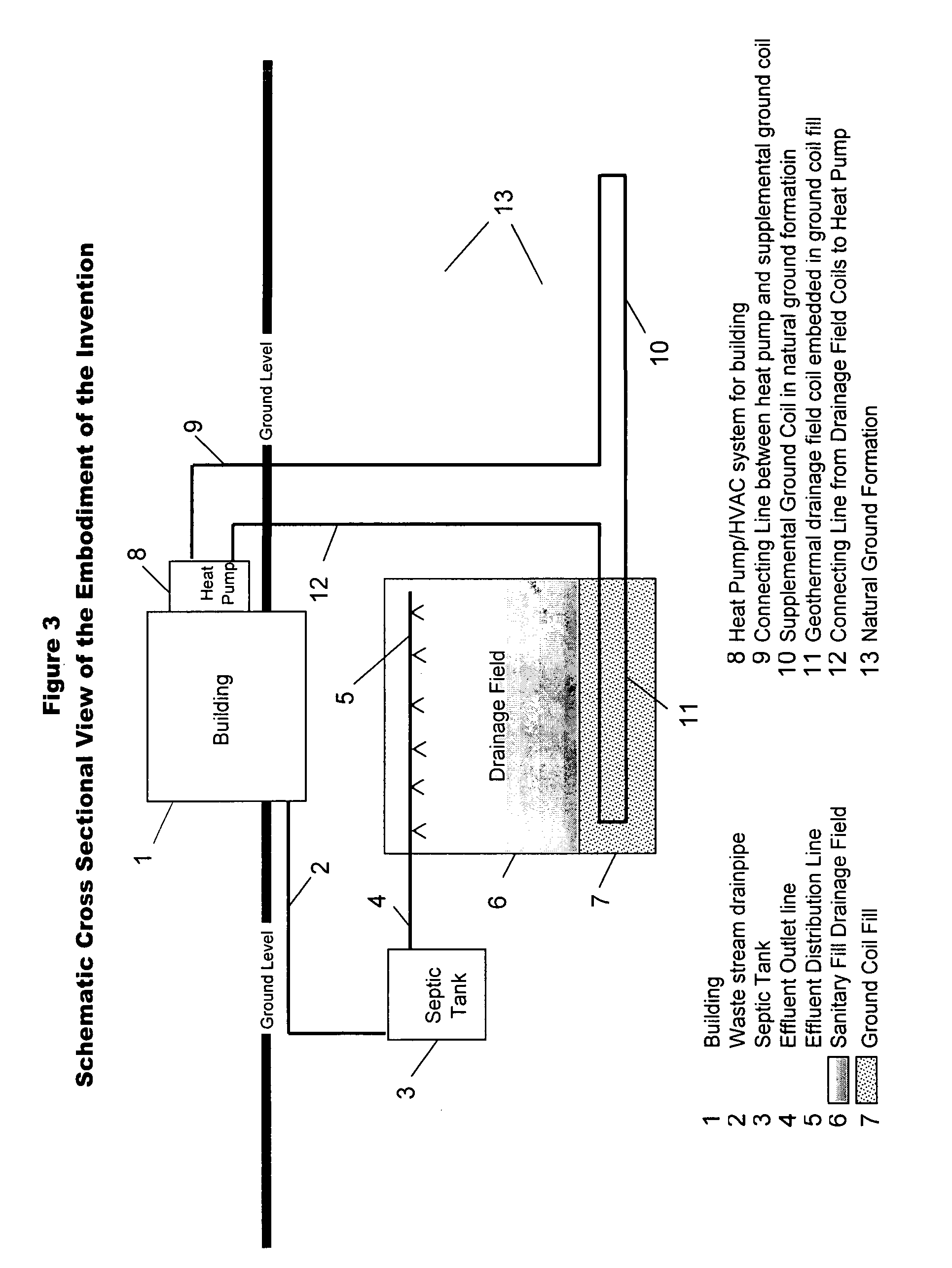
[0016] Referring to FIG. 3, the waste stream from building 1 flows through the waste stream drain pipe 2 into the septic tank 3 where anaerobic bacterial digestion takes place. The effluent form the septic tank, 3 flows through the effluent outlet line 4 into the effluent distribution lines 5 and is distributed into the sanitary fill drainage field 6. The effluent percolates through the effluent drainage field 6 where it is subjected to further bacterial digestion and is clarified by the filtering action of the sanitary fill in the drainage field 6. As the effluent percolates through the drainage field 6, the temperature of the field rises due to the sensible heat of the effluent and heat from the biological digestion in the septic tank 3 and in the drainage field 6. This in turn causes the temperature of the fill 7 below the drainage field to also rise.

[0017] A circulating water feed heat pump 8 is used to provide heating and air conditioning for building 1. During the heating sea...


PUM


Abstract

Geothermal ground coils are installed and embedded in fill at the bottom of excavations, made for drainage fields associated with septic and other effluent systems, prior to the addition of the drainage field sanitary fill. This configuration eliminates the need for expensive bore holes and provides a ground heat source that is at a higher temperature than natural ground formations due to the supplemental heat imparted to the ground by the drain field effluent Fouling of the outside heat transfer surfaces of the ground coils is also avoided because of the clarifying and filtering action of the drain field fill. This provides an improved ground source heat pump system wherein the installation costs are reduced arid the capacity and efficiency of the system are improved.

Description

REFERENCES CITED [REFERENCES BY][0001]U.S. Patent Documents2,563,262August, 1951Moore 126 / 3444,448,347May, 1984Dunstan 165 / 9095,477,914December, 1995Rawlings165 / 455,533,355July, 1996Rawlings165 / 455,730,208March, 1998Barban165 / 455,738,164April, 1998Hilderbrand165 / 455,758,717June, 1998Grossman165 / 47FIELD OF INVENTION [0002] The present invention relates to heat recovery systems and methods, and more particularly pertains to a system and method for recovery of heat from the ground affected by drainage fields. BACKGROUND OF THE INVENTION [0003] Several prior art patents have utilized the earth as a source of heat and as a heat sink. Commercial geothermal energy systems are available and have been in use for several years. These systems normally utilize a water feed heat pump for both heating and cooling. The circulating fluid that feeds the heat pump flows through tubes that are buried deep in the ground and the circulating fluid uses the ground surrounding the tubes as both a heat sour...

Claims


Application Information

Patent Timeline
IPC IPC(8): F25D23/12F24J3/08F25B13/00
CPCF24J3/08Y02E10/10F25B30/06F24T10/10
Inventor SPADAFORA, PAUL F.SPADAFORA, RONALD M.SPADAFORA, FRANK E.
Owner SPADAFORA PAUL F
Why Eureka
Try Eureka