Biosensor

Active Publication Date: 2006-11-02
CITIZEN WATCH CO LTD
View PDF9 Cites 7 Cited by
  • Summary
  • Abstract
  • Description
  • Claims
  • Application Information

AI Technical Summary

Benefits of technology

[0023] The biosensor of the present invention enables a simple collection of a blood sample according to the two functions provided by the narrowed section as described above. Further, with the centrifugal force against thus collected blood sample, transfer thereof to the analytical area can be performed in a simple manner, and in addition, a component extraction can be performed easily. The biosensor according to the present invention transfers the sample sucked into the suction cavity to the analytical cavity through the narrowed section provided in the flow channel, and at the time of centrifugal operation, it is possible to move the whole sample sucked in the suction cavity to the analytical cavity, thereby preventing a decrease of sample as a target for analysis, as well as preventing an external contamination due to spattering of the sample to the outside.
[0042] In the biosensor according to the present invention, only one rotating motor enables two actions, i.e., transfer of the blood sample to the analytical position and separation of the blood by component, and thus extremely simple mechanism has been achieved.

Problems solved by technology

In practice, however, due to busyness and negligence in daily life, a patient often fails to sufficiently control his or her own life for oneself.
Therefore, in many cases, the condition is getting worse.
Furthermore, it is extremely difficult and may be impossible for a medical worker to check whether or not the patient actually carries out the advised details in his or her daily life.
A method which allows a patient to collect blood at home for oneself is limited to a particular method such as obtaining an extremely small amount of blood by stabbing a fingertip or an arm with puncure needle, as is the case using the SMBG device.
Therefore, there has been a problem that concentration measurement cannot be performed accurately.
In addition, there is also a problem that if the biosensor has a structure that sucks the sample into the suction cavity via the capillary phenomenon from the suction port to the air vent, and the centrifugal operation is forced to be performed on this biosensor, the blood sample may spatter from the suction port or the air vent.
Therefore, there is a problem that peripheral equipment is grown in size and not suitable for at-home use equipment.
However, in the conventional arts as described above, there is a problem that it is difficult to perform the blood component analysis with a simple structure.

Method used


Image

  • Biosensor
  • Biosensor
  • Biosensor

Examples


second embodiment

[0052]FIG. 10A is a plan view and FIG. 10B is a cross sectional view of a lower plate of the biosensor according to the present invention.

[0053]FIG. 11 is an explanatory view to explain the biosensor according to the second embodiment of the present invention.

[0054]FIG. 12A and FIG. 12B are schematic cross sectional views to explain bonding of upper and lower plates by ultrasonic welding.

third embodiment

[0055]FIG. 13A and FIG. 13B are explanatory views to explain the biosensor according to the present invention.

[0056]FIG. 14A, FIG. 14B, and FIG. 14C are explanatory views to explain the biosensor according to the third embodiment of the present invention.

[0057]FIG. 15A, FIG. 15B, and FIG. 15C are explanatory views to explain the biosensor according to the third embodiment of the present invention.

[0058]FIG. 16A, FIG. 16B, and FIG. 16C are explanatory views to explain the biosensor according to the third embodiment of the present invention.

[0059]FIG. 17A, FIG. 17B, and FIG. 17C are explanatory views to explain the biosensor according to the third embodiment of the present invention.

[0060]FIG. 18A and FIG. 18B are illustrations to explain manual application of centrifugal force to the biosensor.

DETAILED DESCRIPTION

first embodiment

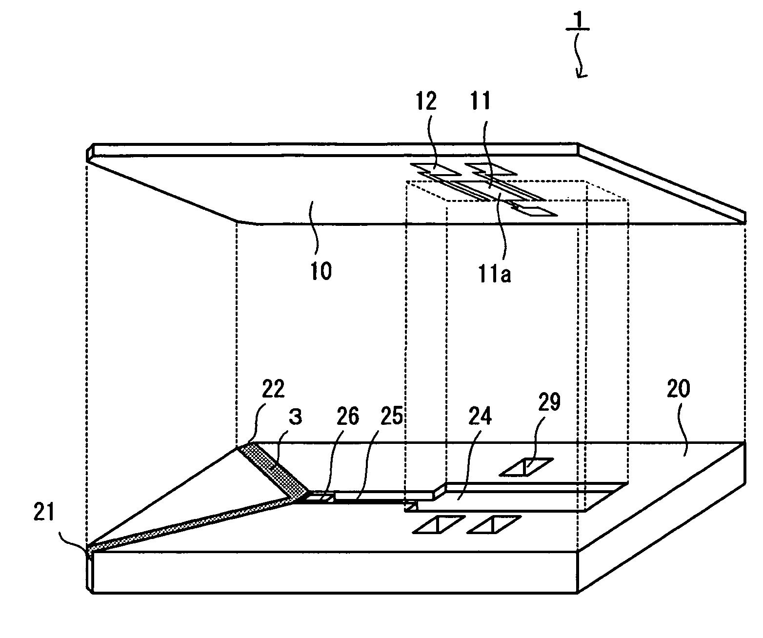
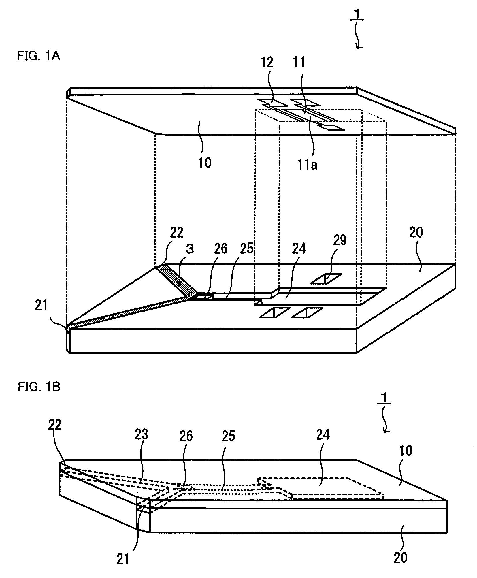
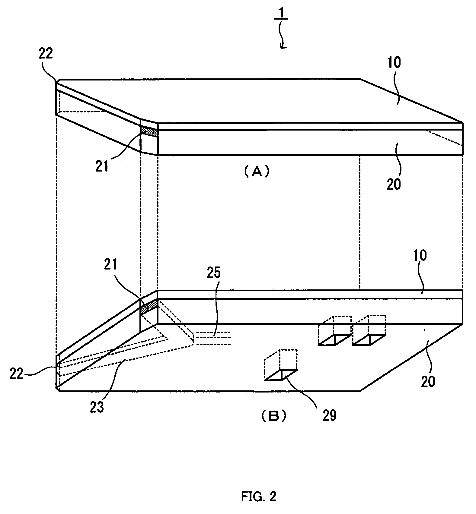
[0061] Initially, a biosensor according to the present invention will be explained. FIGS. 2A and 2B are external views each showing one embodiment of the biosensor according to the present invention. The biosensor 1 has a structure that a lower plate 20 and an electrode substrate 10 are bonded together. FIG. 2A is an illustration of the biosensor viewed from the electrode substrate 10 side, and FIG. 2B is an illustration of the biosensor viewed from the lower plate 20 side.

[0062] A suction port 21 is provided on one side surface of the biosensor 1, and an air vent 22 is provided on the other side surface. There is provided a cavity from the suction port 21 to the air vent 22, the cavity being formed by a portion sandwiched between the lower plate 20 and the electrode substrate 10. This cavity is a suction cavity 23, which is a space to suck a sample such as a certain amount of blood and to retain the sample temporarily. This biosensor is configured such that blood as a sample is suc...


PUM

PropertyMeasurementUnit
Forceaaaaaaaaaa
Centrifugal forceaaaaaaaaaa
Areaaaaaaaaaaa

Abstract

The present invention is directed to a biosensor being provided with a suction cavity which sucks a certain amount of sample by means of capillary phenomenon, the biosensor including a flow channel to connect the suction cavity and an analytical cavity furnished with a reagent, wherein, the flow channel has a narrowed section provided with a gap formed by narrowing a flow passage area. The narrowed section has a function to retain the sample in the suction cavity when the sample is sucked therein, and a function to circulate the sample retained in the suction cavity into the analytical cavity through the gap, when a centrifugal force is applied from the outside. The two functions held by the narrowed section enables a simple collection of blood sample, and further enables a simple transfer of the blood sample to the analytical area by applying the centrifugal force to the blood sample, as well as facilitating a component extraction.

Description

DETAILED DESCRIPTION [0001] 1. Field of the Invention [0002] The present invention relates to a biosensor having a structure for collecting a sample, and for transferring the sample thus collected to an analytical part. [0003] 2. Related Art [0004] In recent years, due to a change in lifestyles, the number of patients with high-blood pressure, diabetes, and / or hyperlipemia is on the increase. These diseases are called as lifestyle-related diseases, and those may act as risk factors of arteriosclerosis. National and local governments are aiming at reducing mortality rate of stroke, that of ischemic heart disease, and of total cardiovascular disease, by modifying lifestyles. [0005] Daily life control is an important approach for treating the lifestyle-related disease, and medical workers such as doctor, nurse, and pharmacist provide various advices on treatment. [0006] In practice, however, due to busyness and negligence in daily life, a patient often fails to sufficiently control his...

Claims


Application Information

Patent Timeline
IPC IPC(8): G01N33/487
CPCG01N27/3272C12Q1/001
Inventor EGAWA, SHUNJI
Owner CITIZEN WATCH CO LTD
Why Eureka
Try Eureka