
Multi-table CT or MRI scanner arrangement for increasing patient throughput

a multi-table, patient-friendly technology, applied in the field of medical imaging system, can solve the problems of limited patient throughput and limiting productivity, and achieve the effects of improving patient care, reducing the high cost of imaging devices, and increasing scan productivity or throughpu

Inactive Publication Date: 2006-11-23
RES FOUND OF STATE UNIV OF N Y THE
View PDF5 Cites 35 Cited by
  • Summary
  • Abstract
  • Description
  • Claims
  • Application Information

AI Technical Summary

Benefits of technology

[0006] The present invention addresses the above and other issues by providing a medical imaging system with increased scan productivity or throughput. The invention allows hospitals and other medical facilities to ameliorate the high cost of imaging devices such as CT or MRI scanners while improving patient care and lowering per-patient costs.
[0007] For example, one CT or MRI scanner with one gantry and two or more patient tables should increase productivity and revenue at less cost than acquiring two conventional CT or MRI scanners, each having one gantry and one table. Although the initial cost to set-up the medical imaging system can be higher than with conventional approaches due to increased floor space and construction requirements, the additional revenue generated by the increased throughput can rapidly justify the higher initial outlay.
[0008] Additionally, patient care is enhanced by providing faster patient access to the imaging device, and by maintaining the patient on one patient table throughout the imaging and pre- and post-processing.
[0013] In another aspect, a medical imaging system includes a medical imaging device, and a rotating carousel that carries at least one patient table / tabletop in a track, where the medical imaging device is located at a central region within the carousel. A patient can be processed at a processing area outside the carousel before the associated patient table / tabletop is guided by tracks onto the carousel when the carousel is stationary. The carousel is rotated until the patient table / tabletop reaches an access point to the medical imaging device. The patient table / tabletop is then guided radially inward by tracks to the central region for imaging. A folding shielded door can be arranged to separate the carousel from the area in which the medical imaging device is located. When the imaging is complete, the patient table / tabletop is guided radially outward, through the access point, back to the carousel. The carousel is rotated until the patient table / tabletop reaches the processing area, where the patient table / tabletop is guided radially outward and unloaded into the processing area. Additional processing areas can also be provided. A given patient can be loaded into the carousel at one processing station and unloaded at another, for example. Furthermore, a mirror image of the above arrangement can also be used, where an additional access point is provided on the other side of the medical imaging device. In this case, two patient tables / tabletops can be arranged in the central region at the same time, thereby allowing further increased patient throughput.

Problems solved by technology

Patient throughput is limited by the time it takes to place a patient on the patient table, prep the patient for the scan, perform the scan (scan time), take the patient off the table, and clean and prepare the table for the next patient.
What primarily limits productivity are pre and post scan procedures such as preparing the patient, placing the patient on the patient table, taking the patient off the patient table and preparing the scanner for the next patient.

Method used


Image

  • Multi-table CT or MRI scanner arrangement for increasing patient throughput
  • Multi-table CT or MRI scanner arrangement for increasing patient throughput
  • Multi-table CT or MRI scanner arrangement for increasing patient throughput

Examples


Embodiment Construction

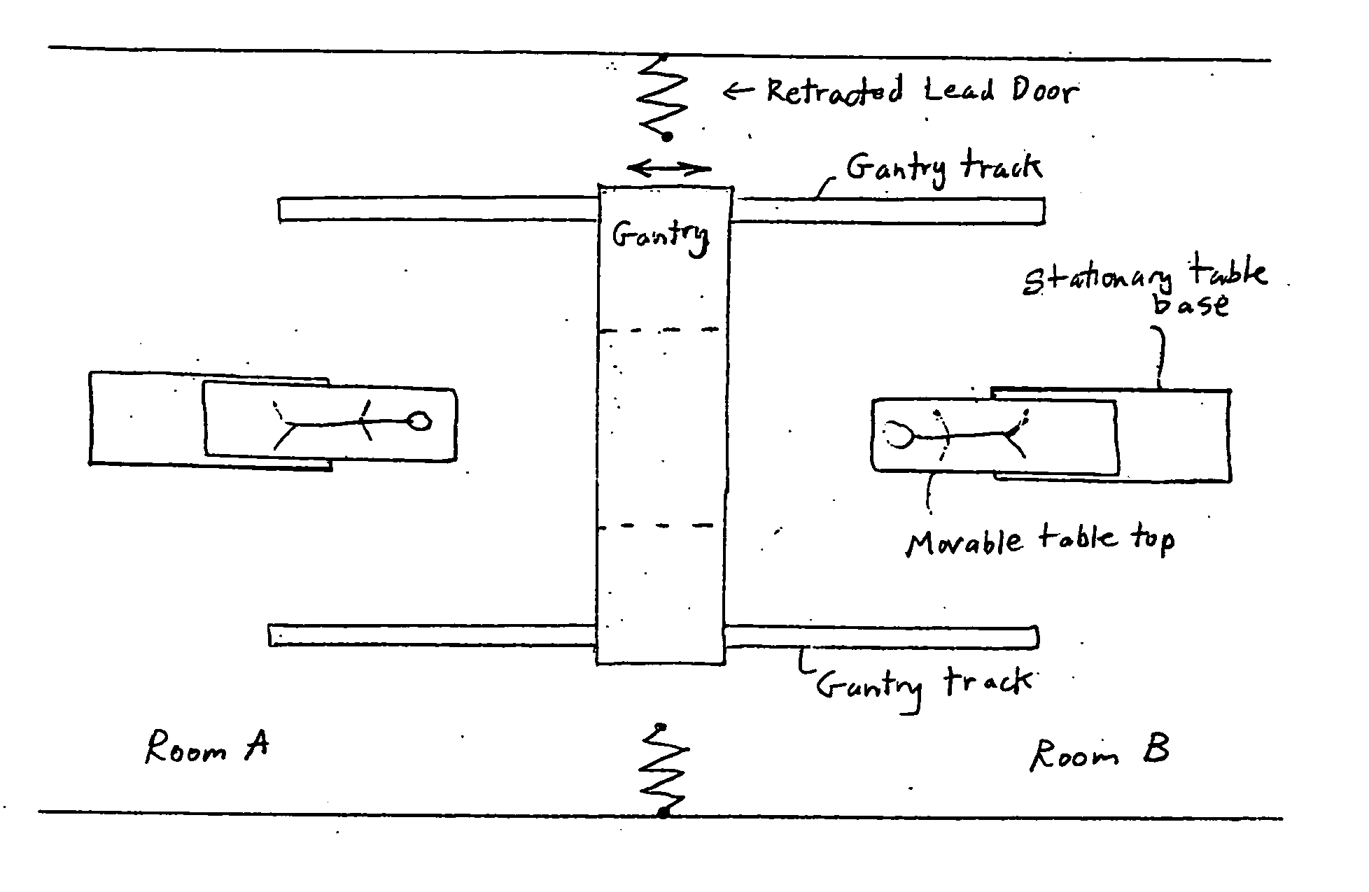
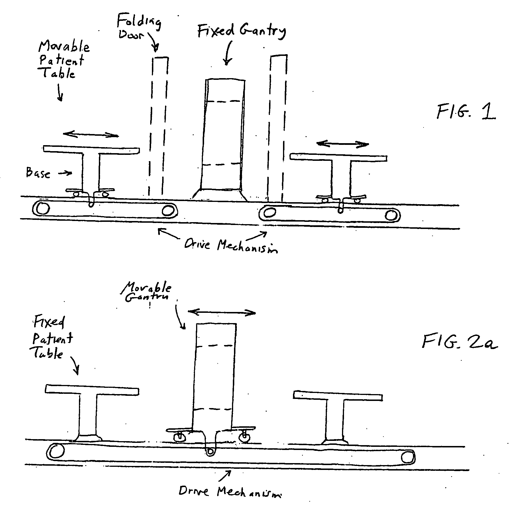
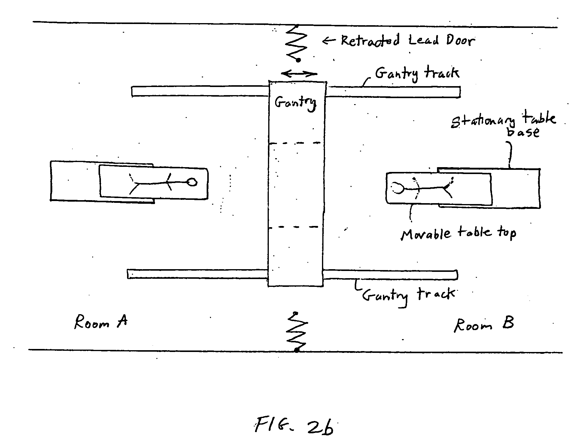
[0026] Conventional medical imaging devices such as CT and MRI scanners have one scanner gantry and one patient table, also referred to as a scanner table. In order to increase scanner productivity and patient throughput, a scanner gantry with two or more patient tables is proposed. The scan can be performed by moving the scanner gantry over the patient on the patient table, moving the patient table through the gantry, or some other arrangement linking the multiple patient tables to the scanner gantry. One CT / MRI scanner with one gantry and two or more tables should increase productivity and revenue at less cost than acquiring two conventional CT / MRI scanners, each having one gantry and one table. Various illustrative arrangements are provided below.

[0027]FIG. 1 illustrates a side view of a medical imaging system having a fixed medical imaging device and movable patient tables guided by floor tracks on each side of the medical imaging device. In this approach, a patient table is pr...


PUM


Abstract

A medical imaging system with increased scan productivity or throughput. The invention allows hospitals and other medical facilities to ameliorate the high cost of imaging devices such as CT or MRI scanners while improving patient care and lowering per-patient costs. A single imaging device is arranged so that pre- or post-imaging processing of one or more patients and patient tables / tabletops can be performed simultaneously with imaging of another patient. The imaging device can be stationary, while patient tables / tabletops are movably guided by tracks on both sides of the imaging device. The imaging device can also be movable relative to the patient tables / tabletops. An overhead or floor track system can be used such as a circuit, or multiple track branches that merge at a junction. Or, the imaging device can be located at the center, or outside, of a carousel on which the patient tables are loaded and unloaded.

Description

CROSS REFERENCE TO RELATED APPLICATIONS [0001] The present application claims benefit of U.S. Provisional Application No. 60 / 651,337 filed Feb. 9, 2005.BACKGROUND OF THE INVENTION [0002] 1. Field of Invention [0003] The invention relates generally to a medical imaging system with increased patient throughput. [0004] 2. Description of Related Art [0005] Conventional medical image devices such as computed tomography (CT) and magnetic resonance imaging (MRI) scanners have one scanner gantry and one patient table. Patient throughput is limited by the time it takes to place a patient on the patient table, prep the patient for the scan, perform the scan (scan time), take the patient off the table, and clean and prepare the table for the next patient. Scan time was prolonged on early scanners. However, on modern day scanners, scan time is significantly reduced. For example, a multislice CT scanner can perform a scan in the range of seconds to minutes. Scan time is therefore no longer a sig...

Claims


Application Information

Patent Timeline
Patent Type & Authority Applications(United States)
IPC IPC(8): A61G7/10
CPCA61B6/0457A61B5/0555A61B6/0487A61B5/055A61B5/704
Inventor MANZIONE, JAMES V.
Owner RES FOUND OF STATE UNIV OF N Y THE
Learn More