Method for the combustion of a fluid fuel, and burner, especially of a gas turbine, for carrying out said method

a technology of fluid fuel and burner, which is applied in the direction of machine/engine, capillary burner, metal/metal-oxide/metal-hydroxide catalyst, etc., can solve the problem that the reaction time available for the secondary reaction after deducting the autoignition time is too short for co-free combustion, and achieves low levels of pollutant emissions

Inactive Publication Date: 2006-11-23
SIEMENS AG
View PDF13 Cites 7 Cited by
  • Summary
  • Abstract
  • Description
  • Claims
  • Application Information

AI Technical Summary

Benefits of technology

[0012] The object of the invention is to indicate a method for burning a fluid fuel by means of which as complete a conversion as possible of the fluid fuel can be achieve...

Problems solved by technology

There is also the problem with practicable existing dimensions that even with partial catalytic conversion the react...

Method used


Image

  • Method for the combustion of a fluid fuel, and burner, especially of a gas turbine, for carrying out said method
  • Method for the combustion of a fluid fuel, and burner, especially of a gas turbine, for carrying out said method
  • Method for the combustion of a fluid fuel, and burner, especially of a gas turbine, for carrying out said method

Examples


Embodiment Construction

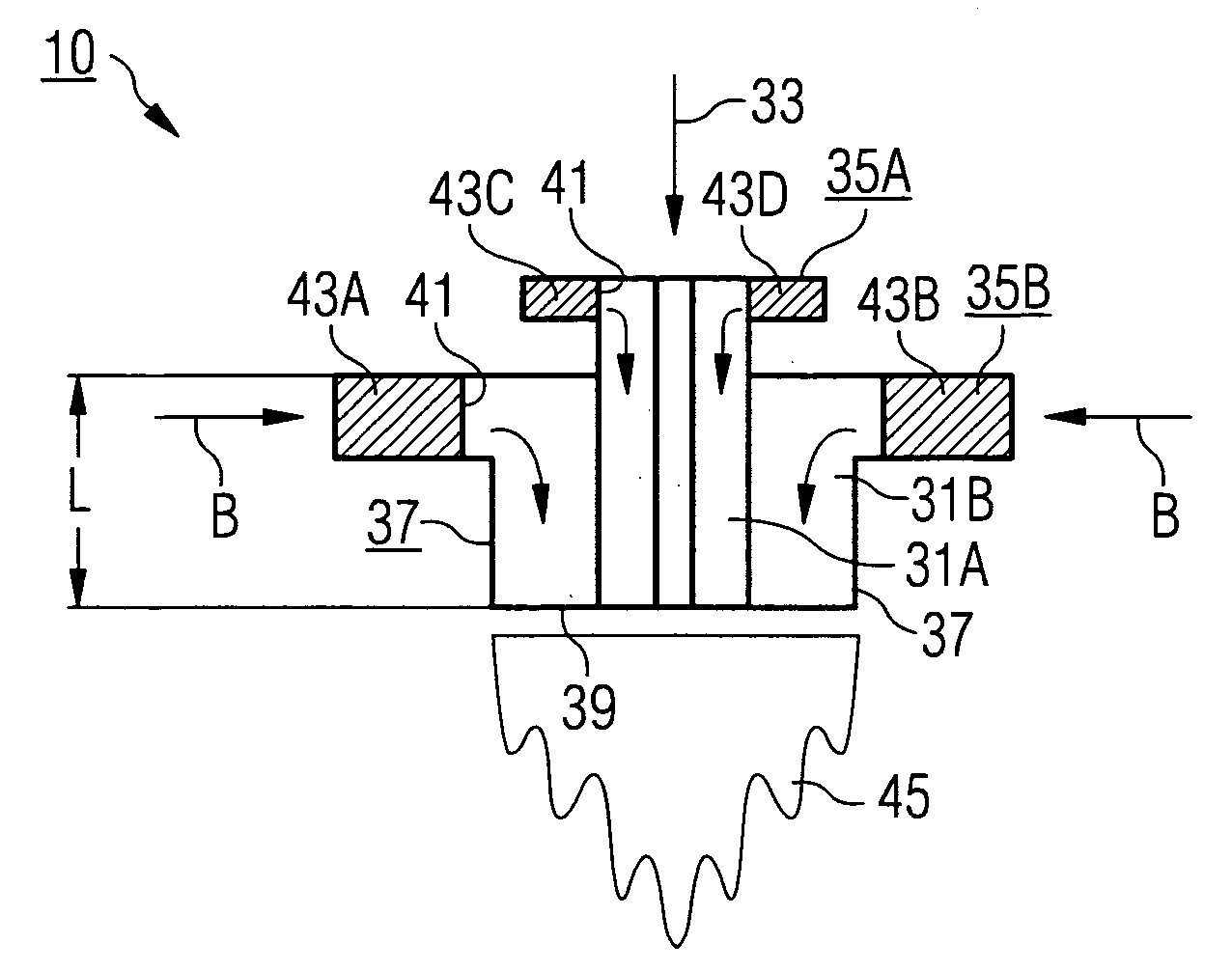
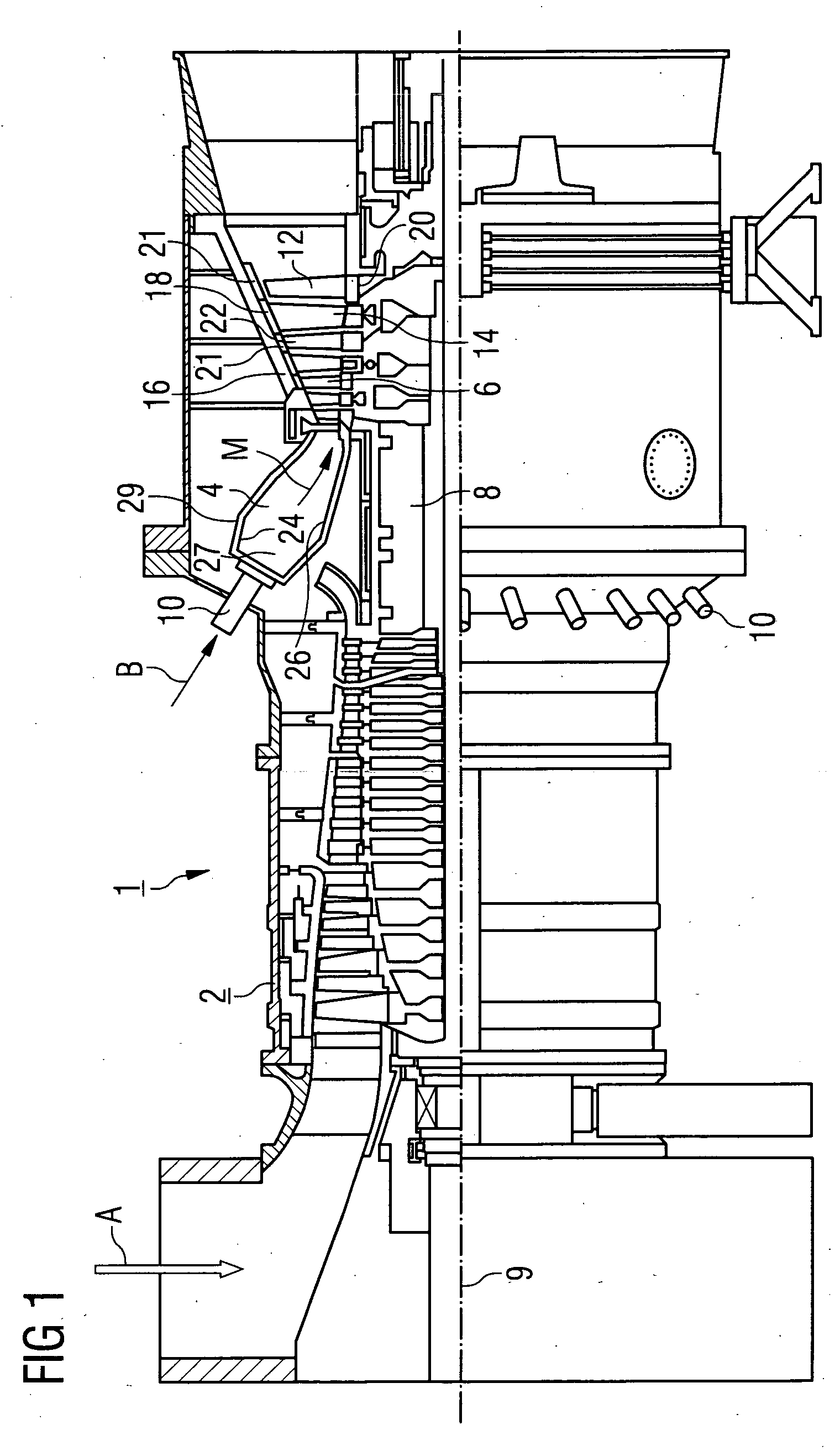
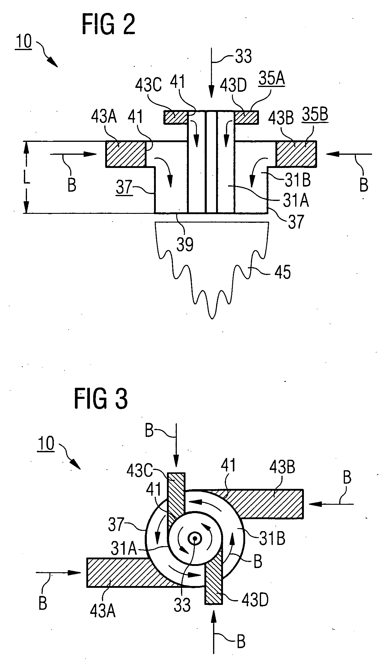
[0038] The gas turbine according to FIG. 1 has a compressor 2 for combustion air, a combustion chamber 4 and a turbine 6 for driving the compressor 2 and a generator or a machine not shown in detail. To this end, the turbine 6 and the compressor 2 are arranged on a common turbine shaft 8, also called a turbine rotor, to which the generator or the machine is also connected and which is pivoted about its central axis 9. The combustion chamber 4, fashioned in the manner of an annular combustion chamber, is equipped with a number of burners 10 for burning a liquid or gaseous fuel. The burner 10 is fashioned as a catalytic combustion system and designed for a catalytic and a non-catalytic combustion reaction or combinations thereof. The structure and mode of operation of the burner 10 will be discussed in greater detail in connection with FIGS. 2 and 3.

[0039] The turbine 6 has a number of rotatable moving blades 12 connected to the turbine shaft 8. The moving blades are arranged on the ...


PUM

PropertyMeasurementUnit
Angleaaaaaaaaaa
Angleaaaaaaaaaa
Lengthaaaaaaaaaa

Abstract

The invention relates to a method for burning a fluid fuel, in which fuel is reacted in a catalytic reactions whereupon catalytically pre-reacted fuel continues to be burned in a secondary reaction. A swirling component is impressed onto the pre-reacted fuel, allowing the secondary reaction to be ignited in a spatially controlled manner, resulting in complete burnout. The invention further relates to a burner for burning a fluid fuel, in which the fuel outlet of a catalytic burner is disposed upstream of the fuel outlet of a primary burner in the direction of flow of the fuel within a flow channel such that the fuel is catalytically reacted. The catalytic burner is provided with a number of catalytically effective elements which are arranged such that a vortex is created in the flow channel. The invention can be applied particularly to combustion chambers of gas turbines.

Description

FIELD OF THE INVENTION [0001] The invention relates to a method for burning a fluid fuel, in which fuel is reacted in a catalytic reaction, whereupon catalytically pre-reacted fuel continues to be burned in a secondary reaction. The invention further relates to a burner for burning a fluid fuel, in which the fuel outlet of a catalytic burner is disposed upstream of the fuel outlet of a primary burner in the direction of flow of the fuel within a flow channel, such that the fuel is catalytically reacted. The invention further relates to a combustion chamber which has such a burner and to a gas turbine comprising such a combustion chamber. BACKGROUND OF THE INVENTION [0002] A fluid fuel is understood hereinbelow to refer especially to fuel oil and / or fuel gas, as used especially for gas turbines. Fuel oil is understood to refer to all combustible liquids, e.g. mineral oil, methanol, etc. and fuel gas is understood to refer to all combustible gases, e.g. natural gas, coal gas, synthesi...

Claims


Application Information

Patent Timeline
IPC IPC(8): F23R3/40F23C13/00F23R3/12
CPCF23C13/00F23R3/40F23R3/12F23C13/08
Inventor PRADE, BERND
Owner SIEMENS AG
Why Eureka
Try Eureka