Multilayered steel armour

a technology of multi-layered steel and armour, applied in the direction of armour, protective equipment, armour plates, etc., can solve the problems of easy propagation of cracks, affecting the overall structural integrity of the armour, so as to enhance the overall structural integrity, eliminate deformation, and high adhesion

Inactive Publication Date: 2006-11-30
SVOS
View PDF9 Cites 21 Cited by
  • Summary
  • Abstract
  • Description
  • Claims
  • Application Information

AI Technical Summary

Benefits of technology

[0022] The multilayered steel armour made to the specifications of the herein described invention result into compact armour structure with extremely high level of adhesion, strong metallurgical bond of the individual layers. The advantages of such composed structures manifest themselves in particular during giving these materials desired shape and during the thermal treatment of these materials and products. The joining metallic intermediate layer (or layers as case may be) due to their high plasticity eliminates deformations due to structural, thermal and dimensional changes taking place in the individual armour layers.
[0023] In addition to the above advantage of the multilayered steel armour according to the invention the other substantial advantage of these armoured plates manifest itself in the realm of their ability to withstand extremes of ballistic loads. The joining metallic intermediate layer represents an efficient barrier in the way of propagation of cracks between the individual armour layers whereby significantly enhancing the overall structural integrity of the armour.

Problems solved by technology

The common disadvantage of all these two-layered steel armour plated is the widely different physical and technological properties of the front and the backing layer resulting in a considerable and undesirable changes of shape of the two-layered armor plates taking place both during their manufacturing process giving the plates the basic shape and during the thermal treatment of the completed and deployed armor.
Another and very serious disadvantage of these two-layered armor plates is an ease with which the cracks are able to propagate themselves through the mass of the armour material once under a severe ballistic load.

Method used


Image

  • Multilayered steel armour
  • Multilayered steel armour

Examples


example 1

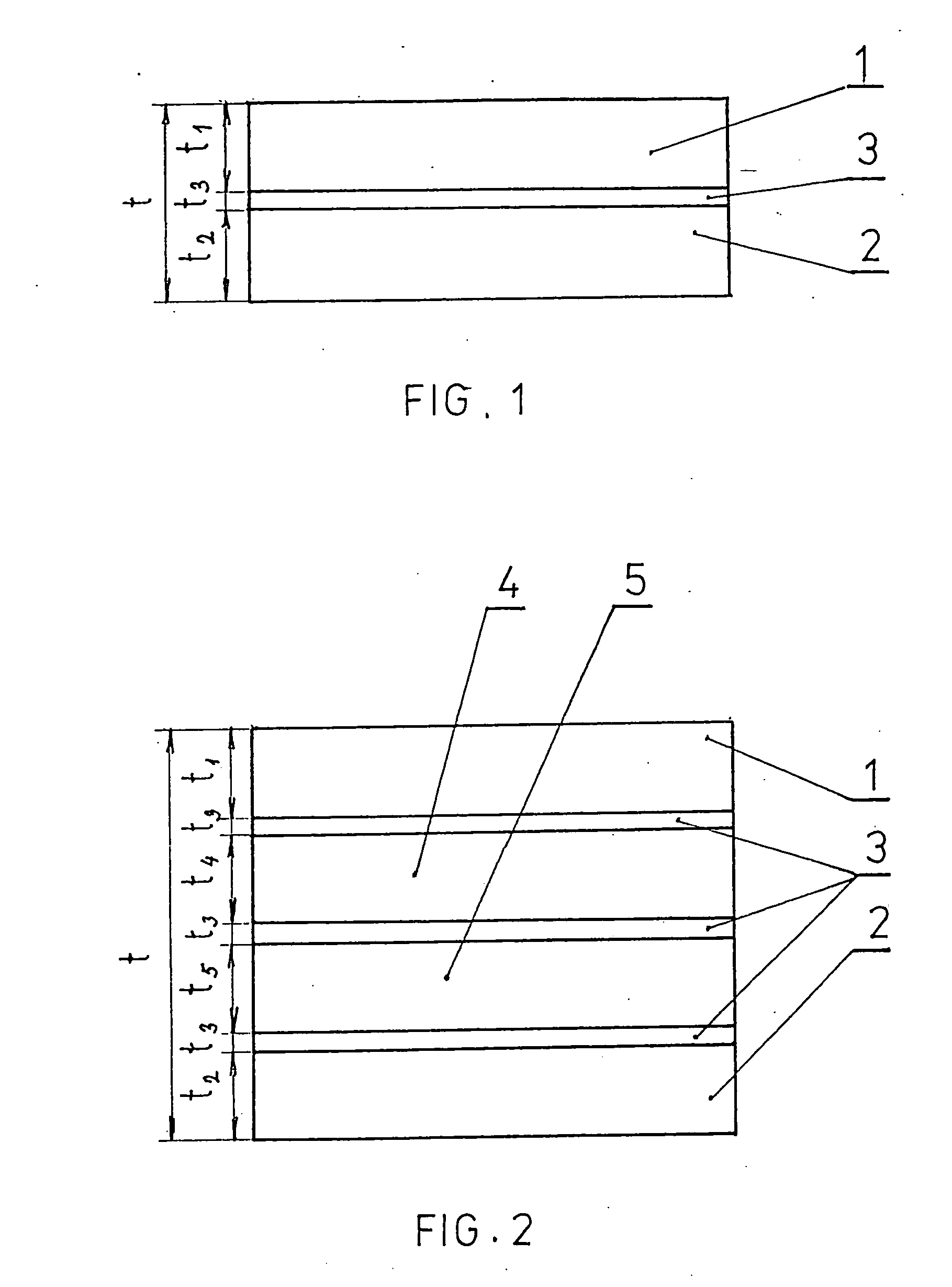
[0028] Multilayered steel armour according to this example, as in FIG. 1, comprises from the front-face ballistic-resistant layer 1 and from the backing armour layer 2.

[0029] The front-face ballistic-resistant armour layer 1 is made from steel alloy containing 0.66 wt % of carbon, 0.40 wt % of silicone, 0.40 wt % of manganese, no more than about 0.010 wt % of phosphorus, no more than about 0.010 wt % of sulfur, 1.20 wt % of chromium, 0.20 wt % of nickel, 0.20 wt % of vanadium, 1.90 wt % of tungsten, while the rest is iron and other accompanying elements and impurities.

[0030] The backing armour layer 2 is made from the steel alloy containing 0.30 wt % of carbon, 1.60 wt % of silicone, 1.40 wt % of manganese, no more than about 0.010 wt % of phosphorus, no more than about 0.008 wt % of sulfur, 0.40 wt % of chromium, 1.20 wt % of nickel, the rest is iron and other accompanying elements and impurities.

[0031] There is the joining metallic intermediate layer 3 located between the front...

example 2

[0034] Multilayered steel armour in this example represents the alternative implementation of the multilayered steel armour from the first example with the changed material of the inserted joining metallic intermediate layer 3. The material of this layer 3 was changed to the austenitic structure containing 10.6 wt % of nickel, 16.7 wt % of chromium, 2.2 wt % of molybdenum, 1.7 wt % of manganese, 0.5 wt % of silicone, 0.4 wt % of titanium, 0.03 wt % of carbon with the rest being iron and other usual admixtures and impurities.

[0035] This multilayered steel armour is prepared using the technology of multilayered casting, which is followed by the elevated temperature rolling process. The total thickness t of this multilayered steel armour is 7.5 millimeters, the thickness t1 of the front-face ballistic-resistance armour layer 1 is 3.5 millimeters, the thickness t2 of the backing armour layer 2 is 3.6 millimeters and the thickness t3 of the joining metallic intermediate layer 3 is 0.4 m...

example 3

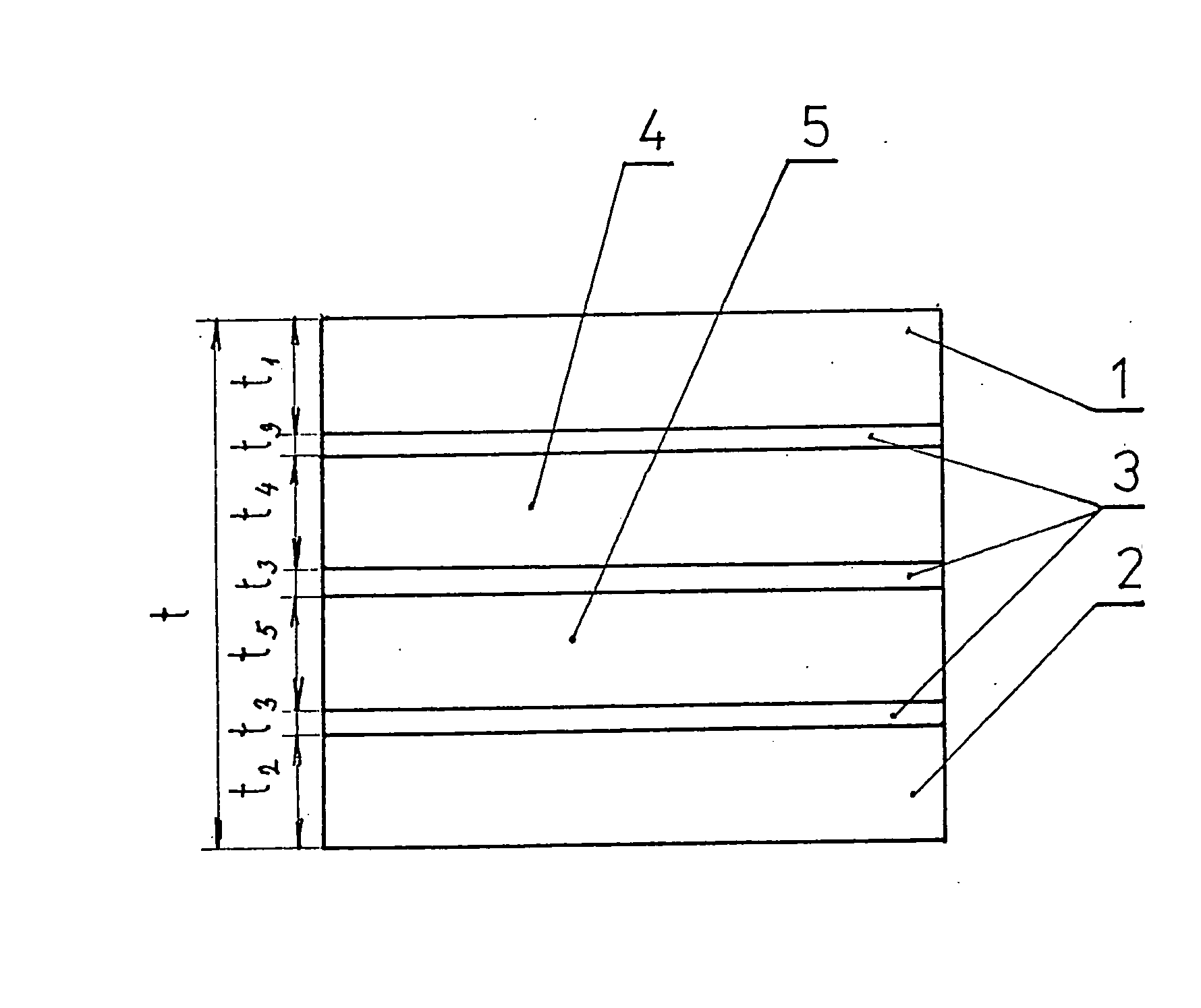
[0036] The multilayered steel armour in this (third) example also represents the alternative implementation of the multilayered steel armour of the type introduced in the example 1. The difference is in a different composition of the joining metallic intermediate layer 3 joining the armour layer 1,2. The material of this layer 3 is the austenitic structure containing 12.5 wt % of manganese, 1.3 wt %. of carbon, 0.4 wt % of silicone while the rest is iron, other accompanying elements and usual impurities.

[0037] The total thickness t of this multilayered steel armour as well as the thickness t1 of the front-face ballistic-resistant armour layer 1 and the thickness t2 of the backing armour layer 2 and finally the thickness t3 of the joining metallic intermediate layer 3 are identical to thicknesses of the example 2.


PUM

PropertyMeasurementUnit
thicknessaaaaaaaaaa
thicknessaaaaaaaaaa
thicknessaaaaaaaaaa

Abstract

The multilayered steel armour consisting of the front-face ballistic-resistant armour layer (1) and the backing armour layer (2), which are fully metallurgically bonded by means of at least one joining metallic intermediate layer (3), for example, by casting, wide-area welding techniques, using technology of explosive cladding (high-velocity impact cladding), by roll welding or by a combination of the previous techniques. The joining metallic intermediate layer (3) between the front-face ballistic-resistant armour layer (1) and the backing armour layer (2) is made from the material featuring the face-centered cubic crystalline lattice (FCC lattice), in particular, from the nickel alloy containing maximally 98.0 wt % of nickel and/or from steel.

Description

FIELD OF THE INVENTION [0001] The invention relates to the multilayered steel armour for both the defense and civilian ballistic protection application. BACKGROUND OF THE INVENTION [0002] The techniques of armouring applied both in civilian and defense realms make use of the various monolithic and / or composite steel armours in the role of assembly components and parts. Hand in hand with the ever-increasing requirements of the degree of the ballistic protection the technical capacity to meet such requirements has become virtually exhausted when only monolithic armour materials are concerned and therefore we have been recently witnessing a gradual shift of emphasis towards the application and use of two-layered materials bonded together. [0003] These two-layered steel armour plates are usually made from a suitable combination of two kinds of materials having quite different properties. The front-face layer intended to break or shatter attacking bullets is usually made from the steel o...

Claims


Application Information

Patent Timeline
Patent Type & Authority Applications(United States)
IPC IPC(8): F41H5/02
CPCF41H5/045
Inventor CERNY, JAROSLAVROLC, STANISLAVPOSPISIL, FRANTISEK
Owner SVOS
Why Eureka
Try Eureka