Apparatus for minimizing a heat affected zone during laser micro-machining

a laser micro-machining and heat-affected technology, applied in metal-working apparatus, welding apparatus, manufacturing tools, etc., can solve the problems of direct decrease in the throughput of the machining process, unsatisfactory material properties, and unacceptable haze, so as to increase the throughput of laser micro-machining and minimize the heat-affected area

Active Publication Date: 2006-11-30
RESONETICS
View PDF15 Cites 17 Cited by
  • Summary
  • Abstract
  • Description
  • Claims
  • Application Information

AI Technical Summary

Benefits of technology

[0008] Accordingly, embodiments of the present invention increase throughput of laser micro-machining by decreasing the ratio of plasma plume volume to machined perimeter length while maintaining the total machining site area. To that end, some embodiments of the invention present methods and systems for minimizing a heated region created during a laser, micro-machining process. This may be accomplished by subdividing (for example) the laser beam into noncontiguous machining elements.

Problems solved by technology

The heat energy in the HAZ can alter the material properties of the un-machined material in an undesirable manner.
When the laser pulse rate is too high, the magnitude and rate of plasma formation cause heating of un-machined material around the machined area causing an unacceptable HAZ.
Although it is possible to reduce the laser pulse rate to allow material cooling between pulses, such a reduction results in a direct decrease in the throughput of the machining process.

Method used


Image

  • Apparatus for minimizing a heat affected zone during laser micro-machining
  • Apparatus for minimizing a heat affected zone during laser micro-machining
  • Apparatus for minimizing a heat affected zone during laser micro-machining

Examples


Embodiment Construction

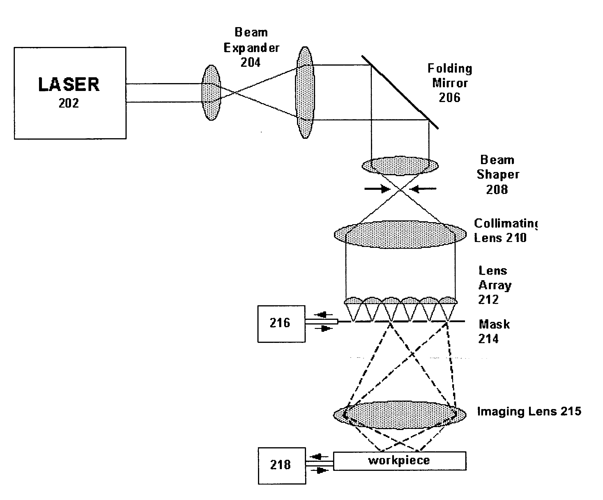
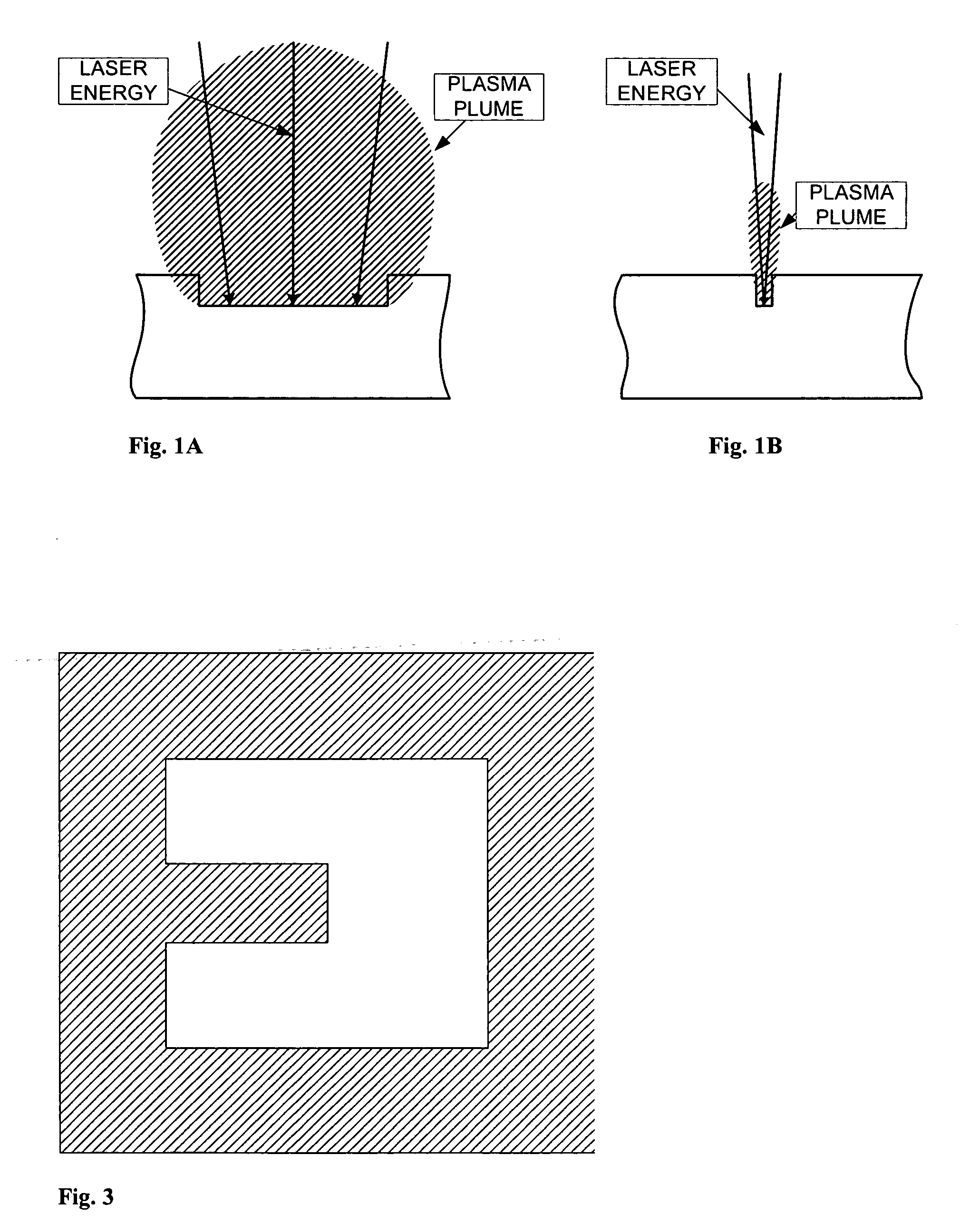
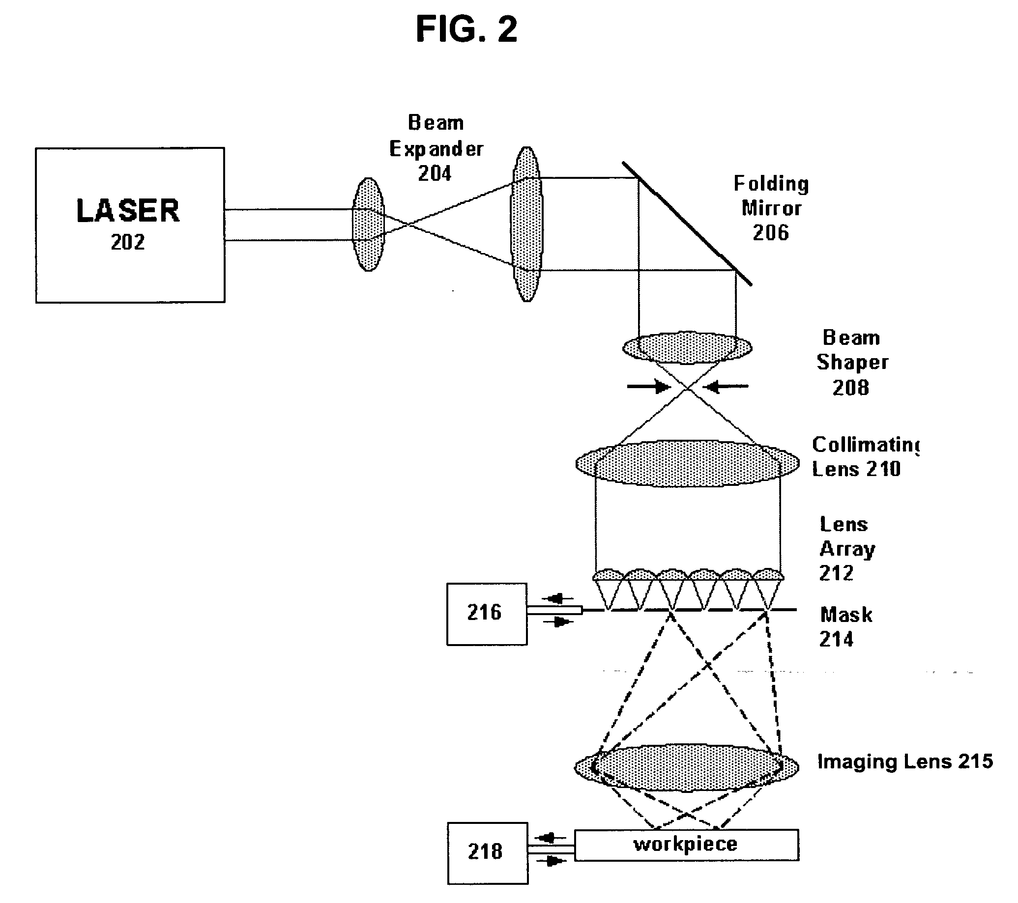
[0022] Embodiments of the present invention enable high throughput laser micro-machining while limiting the size of a laser plume. To that end, an exemplary laser micro-machining apparatus which may be used with embodiments of the present invention is shown in FIG. 2. As shown, an illumination source 202 emits a beam of light (laser beam) which is then expanded with a 2-element telescope 204 (for example) and which may be folded down with a 45 degree mirror 206. The light may then brought to focus at a beam shaping aperture 208. The beam shaping aperture may be used as a mask to create an illumination shape (e.g., square, rectangle, triangle, etc.).

[0023] The beam shaper plane may then be imaged to infinity (for example) by a collimator lens 210, which then may impinge the beam onto an array 212 of lens elements. Each lens element may then intercept a portion of the collimated beam and forms an image of the beam shaper plane at the mask 214. An imaging lens 215 may then be used to ...


PUM

PropertyMeasurementUnit
angleaaaaaaaaaa
angleaaaaaaaaaa
perimeteraaaaaaaaaa

Abstract

Embodiments of the present invention are directed to methods and systems for laser micro-machining, which may include dividing a long line illumination field into a plurality of individual fields, wherein each of the plurality of fields includes an aspect ratio of about 4:1 or greater, directing the plurality of individual fields onto at least one mask, wherein each individual field illuminates a corresponding area on the mask and translating the mask and/or workpiece relative to one another along a scan axis.

Description

RELATED APPLICATIONS [0001] This application is related to pending U.S. application Ser. No. 10 / 839,026, filed May 4, 2004, and U.S. provisional patent application Ser. No. 60 / 468,511, filed May 7, 2003, each disclosure of which, in its entirety, is herein incorporated by reference.FIELD OF THE INVENTION [0002] Embodiments of the present invention are directed to machining processes, and more particularly, to laser micro-machining. BACKGROUND [0003] In micro-machining, a number of different material transformations exist which allow a laser beam to remove or machine material: ionization, melting / boiling, photo-chemical material modification and photo-chemical reaction with process gasses (for example). Material removal is typically accompanied by a plasma plume rising from the surface of the machined regions after a laser pulse is delivered. The duration of the plasma plume is short (typically 1 to 10 microseconds) but it possesses a very high temperature and the ions produced have ...

Claims


Application Information

Patent Timeline
Patent Type & Authority Applications(United States)
IPC IPC(8): B23K26/06B23K26/38
CPCB23K26/0656B23K26/0661B23K26/365B23K26/0676B23K26/0738B23K26/067B23K26/066B23K26/361
Inventor HALL, BRIANHOLBROOK, DAVID S.WALL, DAVID L.
Owner RESONETICS
Why Eureka
Try Eureka