Method and apparatus for generating origin signal of encoder

a technology of origin signal and encoder, which is applied in the direction of ignition automatic control, electric controllers, instruments, etc., can solve the problems of repeatability and bidirectionality, poor performance of methods, etc., and achieve the effect of optimizing (reducing) the zero return time, maintaining compatibility, and convenient for the system

Active Publication Date: 2006-11-30
MITUTOYO CORP
View PDF23 Cites 0 Cited by
  • Summary
  • Abstract
  • Description
  • Claims
  • Application Information

AI Technical Summary

Benefits of technology

[0010] In view of the foregoing problems, various exemplary embodiments of this invention enable origin detection with excellent repeatability, S / N ratio (pulse width), and bidirectionality while maintaining ease of mounting and adjustment.
[0017] According to the present invention, it is possible for users to set an origin point to a necessary position and width flexibly after power-on. Obtaining the origin signal of necessary width, it is therefore possible to secure a sufficient S / N ratio and establish a bidirectional origin.
[0019] The origin detection essentially has to be performed only once at the beginning. In the meantime, numerical control (NC) units to be connected with the encoder have, by specifications, the function of checking the origin signal each time the origin is passed. Thus, if the origin signal is generated and output accordingly by software, it is possible to maintain compatibility with conventional encoders and resolve the positional shift of the origin signal as well. By using software, it is also possible to set the position and the width of the origin signal freely according to the specifications of the NC units.
[0020] In particular, when the rising edge of the scale origin is used as a slowdown watchdog signal (a trigger signal intended for a zero return operation) so that the rise of the origin or that of the origin inverted is put to subsequent use, it becomes possible to program the origin settings with a position and pulse width convenient for the system. This makes it possible to optimize (reduce) the zero return time.

Problems solved by technology

Nevertheless, the method also has had a problem of poor performances in use, including repeatability and bidirectionality.
Even with the technique described in Japanese Patent Laid-Open Publication No. 2003-83771, however, it has been impossible to output an origin pulse that is adaptable to necessary origin pulse widths.

Method used


Image

  • Method and apparatus for generating origin signal of encoder
  • Method and apparatus for generating origin signal of encoder
  • Method and apparatus for generating origin signal of encoder

Examples


Embodiment Construction

[0032] Hereinafter, an exemplary embodiment of the present invention will be described in detail with reference to the drawings.

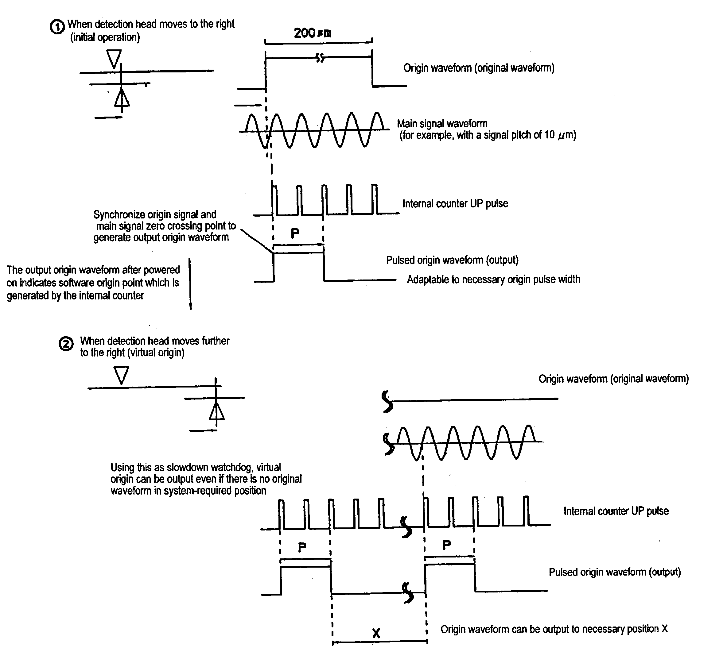
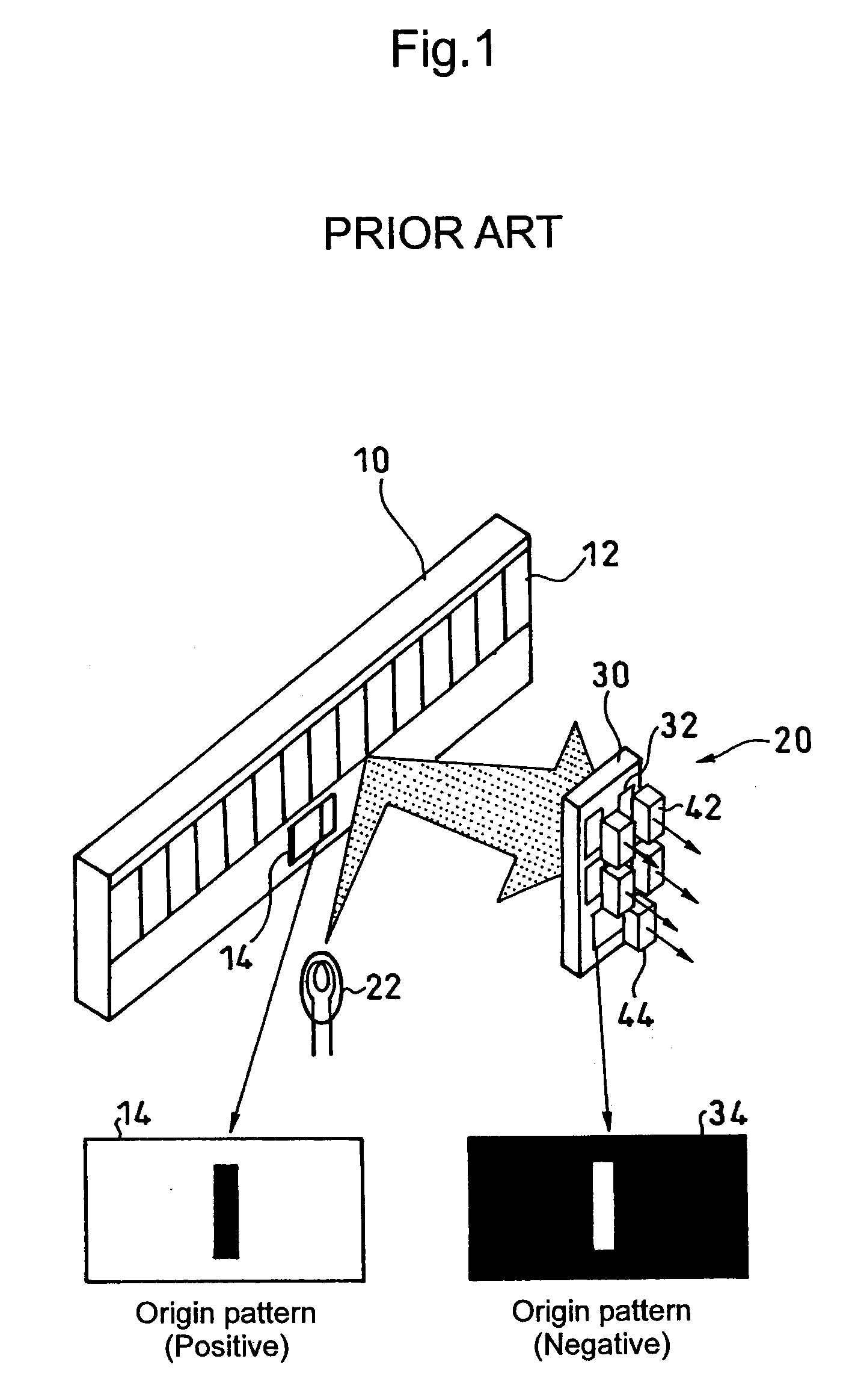
[0033] As shown in FIG. 5, the present exemplary embodiment comprises a scale 10, a detection head 20, a phase division circuit 46, an internal counter 48, a waveform shaping circuit 50, and an origin signal generation circuit 52. The scale 10 has an incremental pattern 12 and an origin pattern 14. The detection head 20 includes an index scale 30 having an incremental pattern 32 and an origin pattern 34, a main signal light-receiving device 42, and an origin light-receiving device 44. The phase division circuit 46 divides the output of the main signal light-receiving device 42 in phase, thereby generating a main signal waveform having a signal pitch of, e.g., 10 μm as shown in FIG. 6A. The internal counter 48 counts up or down in accordance with the main signal waveform that is output from the phase division circuit 46. The waveform shaping circuit 50 shap...


PUM


Abstract

When generating an origin signal of an encoder having a scale on which an incremental pattern and the origin pattern are formed, an origin signal having a necessary position and width is generated by software based on an origin waveform obtained from the origin pattern. This enables origin detection with excellent repeatability, S / N ratio (pulse width), and bidirectionality while maintaining ease of mounting and adjustment.

Description

CROSS-REFERENCE TO RELATED APPLICATION [0001] The disclosure of Japanese Patent Application No. 2005-152224 filed on May 25, 2005 including specifications, drawings and claims is incorporated herein by reference in its entirety. BACKGROUND OF THE INVENTION [0002] 1. Field of the Invention [0003] The present invention relates to a method and an apparatus for generating an origin signal of an encoder that has a scale on which an incremental pattern and an origin pattern are formed. In particular, the invention relates to a method and an apparatus for generating an origin signal of an encoder, by which the origin signal can be generated with high precision irrespective of origin waveforms obtained from the origin pattern. [0004] 2. Description of the Related Art [0005]FIG. 1 shows an encoder that obtains an incremental displacement signal (referred to as main signal) by using a scale 10 on which an incremental pattern 12 is formed. An origin pattern 14 is formed beside the incremental ...

Claims


Application Information

Patent Timeline
Patent Type & Authority Applications(United States)
IPC IPC(8): H04N1/46
CPCG01D5/366G01D5/2457
Inventor ARAI, KOUICHIKODAMA, KAZUHIKO
Owner MITUTOYO CORP
Why Eureka
Try Eureka