
Vector beam generator using a passively phase stable optical interferometer

a phase stable, beam-generating technology, applied in the direction of polarising elements, instruments, photomechanical equipment, etc., can solve the problems of difficult to achieve the same spatial resolution in the axial (or z-) direction, the focusing system is in general limited in its ability to focus light, and the effect is quite problematic, so as to achieve the effect of improving the point spread function

Inactive Publication Date: 2006-11-30
CHICAGO UNIV OF
View PDF9 Cites 60 Cited by
  • Summary
  • Abstract
  • Description
  • Claims
  • Application Information

AI Technical Summary

Benefits of technology

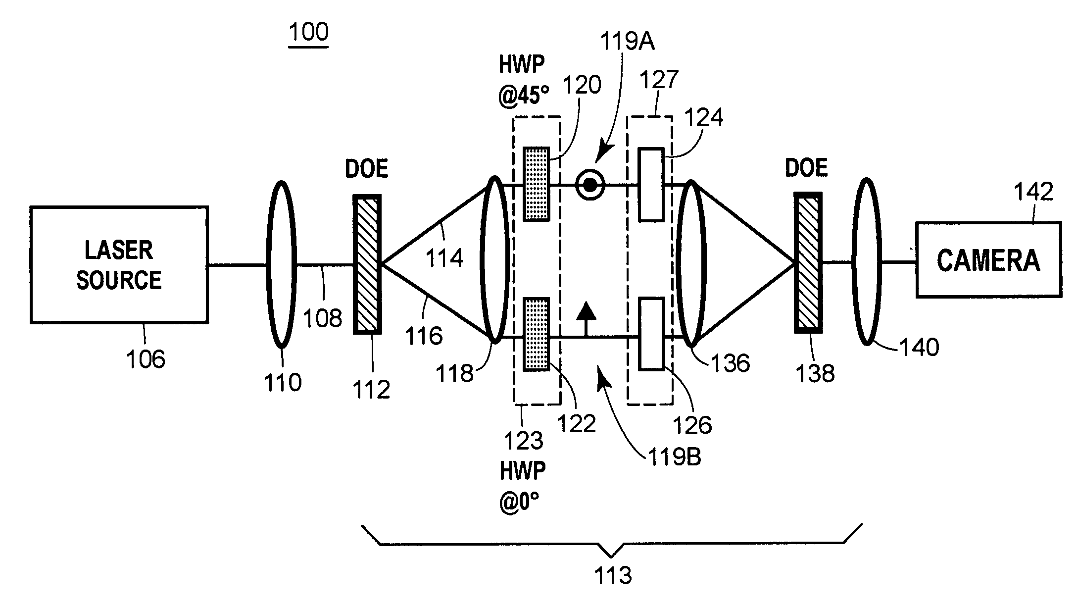
[0011] The setup is robust, and has exhibited passive phase stability (of fringes) for more than three days, making it an attractive light source for microscopy. Preliminary measurements indicate a significant improvement in the point spread function using the radial beam compared to the Gaussian beam.

Problems solved by technology

As known from theory and experiment, focusing systems are in general limited in their ability to focus light.
Focusing systems (e.g. microscope objectives) may be able to tightly confine focused light in a transverse focal (i.e. XY-) plane, but are less able to achieve the same spatial resolution in the axial (or Z-) direction.
For other applications, however, in particular applications with features on the sub-micron and nanometer scale, this effect is quite problematic.
Even these techniques, however, are limited in the tightness of the focus they can achieve.
Heretofore, the techniques for forming vector beam polarized light have been limited in design and in effectiveness.
One challenge to the utilization of vector beams has been the robustness of the method of generation.
Separate approaches based on Mach-Zehnder interferometry or a modified laser resonator have been demonstrated, but these require costly, active phase stabilization techniques.
Alternatively, a spatial light modulator (SLM) has been proposed, but that too is costly and requires the computation of a complex algorithm for the desired phase function.
Also SLM's can result in undesired diffraction effects due to pixelation.
This approach, however, has only demonstrated vector beams at a wavelength of 10.6 μm and has not been used to form frequencies in the visible region.
This technique has been used at visible frequencies, but is quite costly and cumbersome to fabricate.

Method used


Image

  • Vector beam generator using a passively phase stable optical interferometer
  • Vector beam generator using a passively phase stable optical interferometer
  • Vector beam generator using a passively phase stable optical interferometer

Examples


example b

Field Applications

[0063] The vector beams once formed may be used in any number of applications, examples of which include microscopy, including multiphoton microscopy, laser writing, and as a laser tip probe. With azimuthally polarized beams focused using high-NA optics (e.g., 0.75 or higher, such as 0.75 to 1.65), a tightly-focused longitudinally polarized (AC) B-field can be acheived. This AC B-field may be converted to a DC B-field by way of optical rectification. Example applications using the DC magnetic field are numerous.

[0064] An example application is in magnetic storage applications, where the techniques may be used in computer hard drive applications. An azimuthally polarized focused beam, assisted by optical rectification, may produce the necessary B-field strength (coercivity) to read and / or write (in 1, 2, or 3-D through a multifocal, confocal, or holographic approach) into magnetic thin film hard drives. With the tight focusing of the B-field, especially along the ...

example e

Field Applications

[0068] An example application is in improving spatial resolution in microscopy (linear and nonlinear) especially using radially polarized light. Another example is in using the vector beam technique as the front end to generate the optical beam for all conventional linear, confocal, and nonlinear optical microscopes.

[0069] Yet another example is to use a vector beam (particularly radially polarized light) for super-resolution (e.g. 4-Pi) microscopy.

[0070] Another example is generating a longitudinally polarized beam at the focus of a microscope.

[0071] Another example is to generate optical beams with angular momentum.

[0072] Another example is in determining a three-dimensional orientation dipole moment of a single molecule. A z-polarized E-field may be used in conjunction with x- and y-polarized components to determine the absorption or emission dipole moment of the molecule. Measuring field emissions from dipole resonances along each of the component planes w...

example

[0080]FIG. 11 illustrates a focusing apparatus 700 that includes a vector beam generator 702 that may be implemented in accordance with the techniques described above. An output vector beam 704 is coupled to a focusing assembly formed of an objective lens 706, which may be a high-numerical aperture solid hemispherical or other lens or collection of lens elements. In the illustrated example, the vector beam 704 is focused to a focus region 708 in an affected substrate layer 710 on a substrate layer 712. The affected layer 710 may represent an electromagnetically responsive layer, such as a magnetic storage medium that is alterable in response to the application of a magnetic field (B-field). More generally, the layer may represent any magnetic field response material including materials with excitable magnetic dipoles transitionable with high spatial resolution In the example of an azimuthally polarized vector beam 704 (assisted by optical rectification) and a magnetic storage medium...


PUM


Abstract

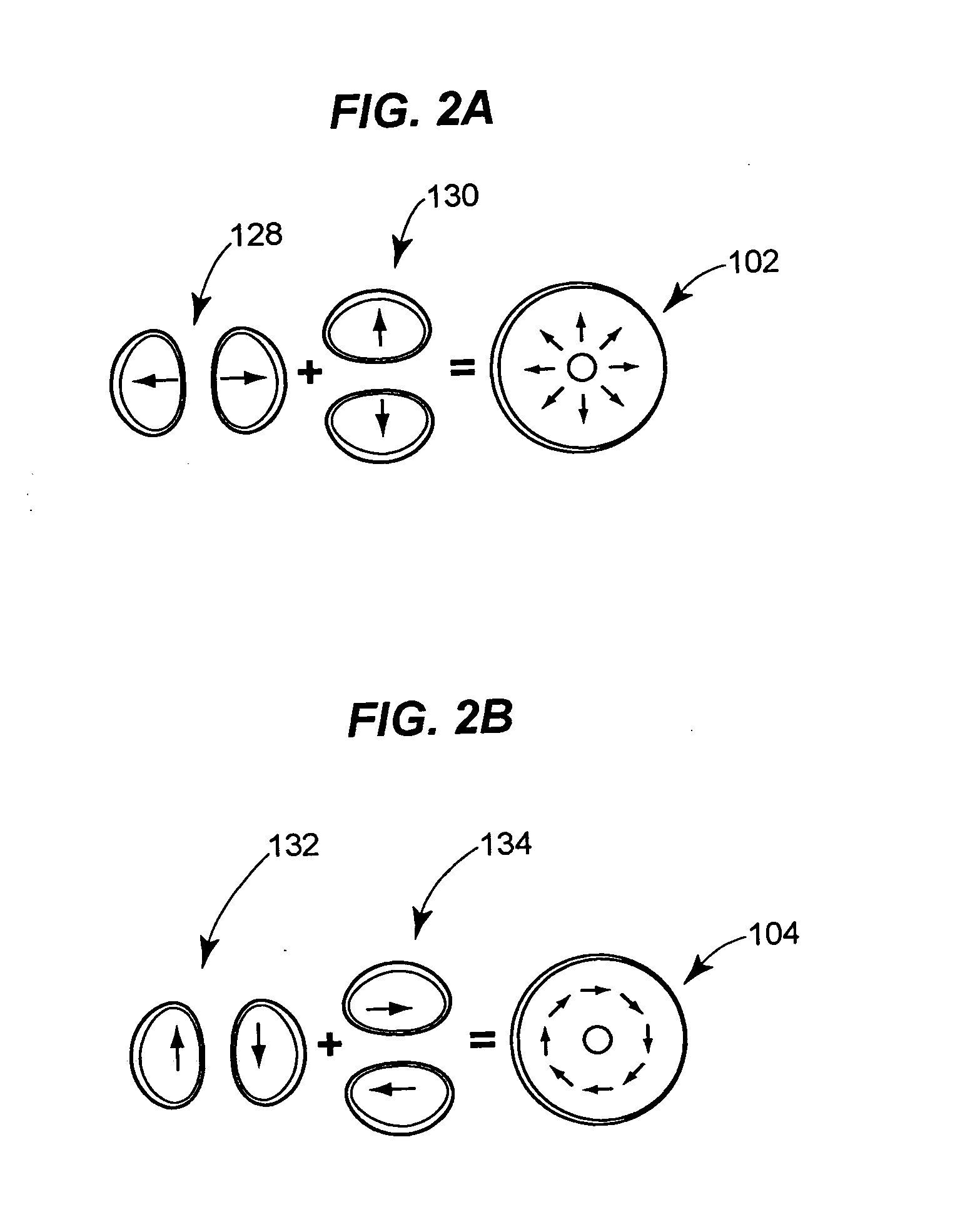
Provided are techniques for generating optical vector beams (e.g., radially and azimuthally polarized light) using passive or active phase stable optical interferometry. Techniques may split an input optical beam into at least two output beams, and then couple those beams simultaneously into a passively phase stable optical interferometer. Beam splitting may be achieved by a diffractive optical element and coupling may be achieved by a single refractive optical device (lenses) or by a single mirror device (e.g., parabolic and spherical). The interferometer may provide the ability to manipulate (or transform) the polarization of part of the wavefront of each beam, as well as the ability to manipulate (or transform) the phase of part of the wavefront of each beam, such that the beams when combined have a vector beam polarization state.

Description

CROSS REFERENCE TO RELATED APPLICATIONS [0001] This application claims the benefit of U.S. Provisional Application No. 60 / 678,344, filed May 6, 2005, the entirety of which is expressly incorporated herein by reference.[0002] Scientific work relating to the invention was supported by Grant Nos. CHE0321232 and CHE0317009 from the United States National Science Foundation and by Grant No. DMR0213745 from the United States National Science Foundation—Materials Research Science & Engineering Centers. The United States government may have certain rights in the invention.BACKGROUND OF THE INVENTION [0003] 1. Field of the Invention [0004] The invention relates generally to techniques for generating polarized light and, more particularly, to techniques for generating vector beams. [0005] 2. Background of Related Art [0006] As known from theory and experiment, focusing systems are in general limited in their ability to focus light. This is commonly referred to as “diffraction limited focusing...

Claims


Application Information

Patent Timeline
IPC IPC(8): G02B27/28G02B5/30
CPCG02B27/286G03F7/70408G03F7/70375
Inventor TOUSSAINT, KIMANI C. JR.SCHERER, NORBERT F.JURELLER, JUSTIN E.PARK, SUNGNAM
Owner CHICAGO UNIV OF
Learn More