Composite membrane and method for forming the same

a technology of polytetrafluoroethylene and composite membrane, which is applied in the field of composite membranes, can solve the problems of limited microfiltration application of eptfe membrane to membrane separation, and achieve the effects of reducing sintering time, preventing serious shrinkage of eptfe membrane, and prolonging the application of ptfe membran

Active Publication Date: 2006-11-30
CHUNG YUAN CHRISTIAN UNIVERSITY
View PDF5 Cites 14 Cited by
  • Summary
  • Abstract
  • Description
  • Claims
  • Application Information

AI Technical Summary

Benefits of technology

[0007] One object of the present invention is to coat a suspension solution of PTFE fine powders on an expanded PTFE membrane, to form porous structure with interconnected channels by a following sintering process that fuses the polytetrafluoroethylene (PTFE) particles. Another object is to perform the sintering process on one side of the ePTFE membrane together with a simultaneous cooling process on the other side, so as to prevent serious shrinking of the ePTFE membrane and to reduce the sintering time via elevating the sintering temperature. The other object is to tailor the gaps among the sintered particles by adjusting the quenching rate of the sintered composite PTFE membrane. With the present invention, composite PTFE membranes can be produced of which the pores are smaller than the ePTFE membranes manufactured by the traditional stretching method. Application of PTFE membranes can therefore be extended, indicating that the present invention has advantages over the traditional method.

Problems solved by technology

However, the application of ePTFE membranes to membrane separation is limited to microfiltration, because the pores generated by stretching are usually larger than 0.1 μm and not uniform.

Method used


Image

  • Composite membrane and method for forming the same
  • Composite membrane and method for forming the same
  • Composite membrane and method for forming the same

Examples


first embodiment

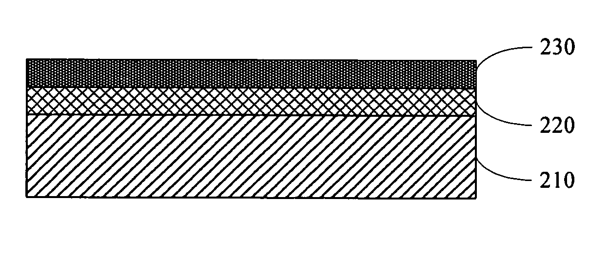
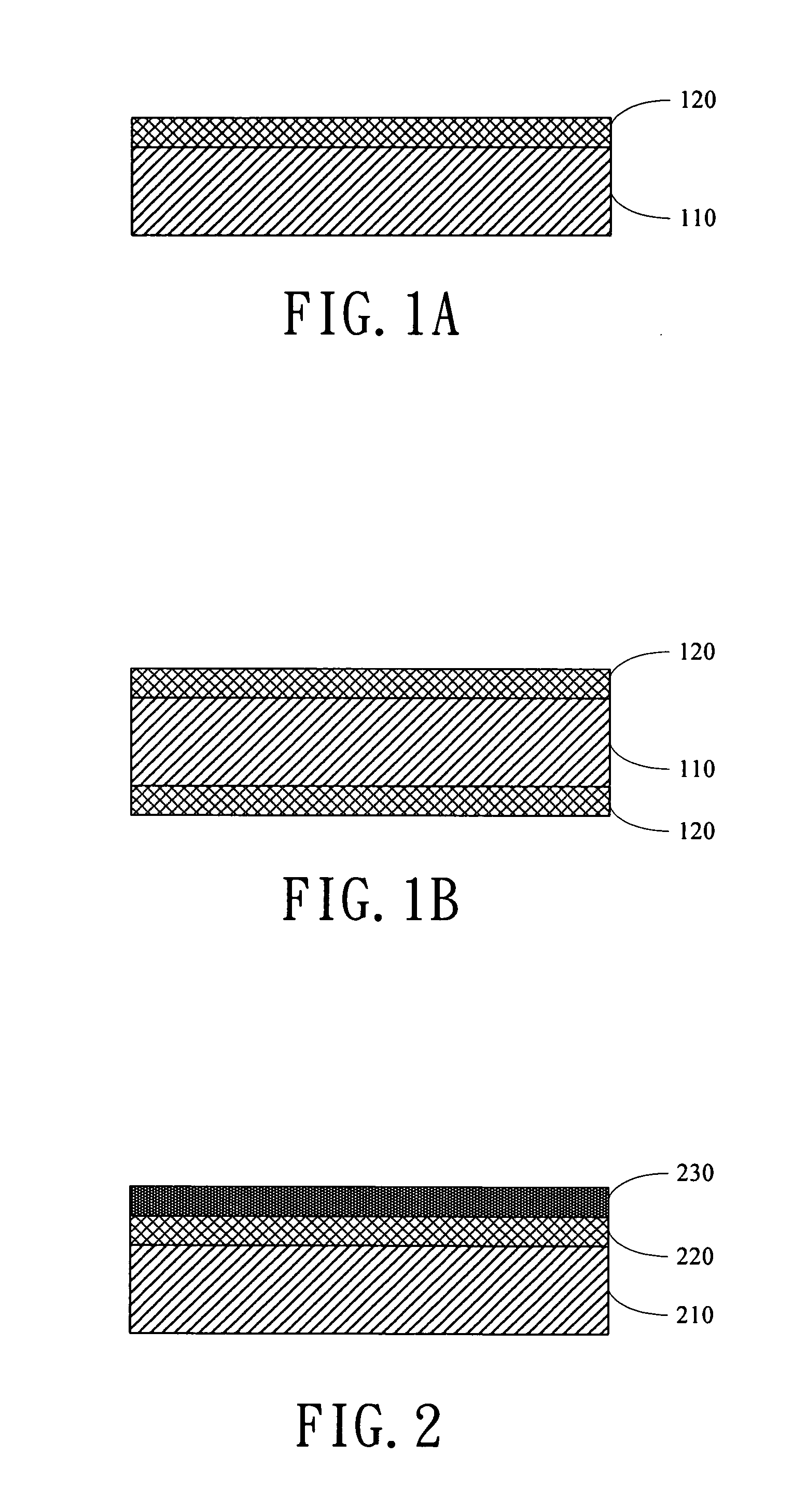
[0014] In the present invention, as shown in FIG. 1A a composite PTFE membrane comprises an expanded PTFE (ePTFE) membrane 110 and a sintered porous PFFE membrane 120, wherein the pore diameter of the ePTFE membrane 110 is about 0.02˜1 μm, the average pore diameter of that is about 0.2˜0.8 μm, and the thickness of that is more than or equal to 10 μm. Moreover, the pore diameter of the porous PTFE membrane 120 is less than or equal to 0.5 μm and the average pore diameter of that is about 0.01˜0.4 μm, which is formed on one surface of the ePTFE membrane 110 by a sintering process. Specifically, the porous PFFE membrane 120 has porous structure with interconnected channels formed by fusing the fine PTFE powders coated on the ePTFE membrane 110, with particle diameter of about 0.01˜1 μm and average diameters of about 0.05˜0.8 μm.

[0015] In this embodiment, the sintering temperature is about 330° C.˜520° C. and the sintering time is less than or equal to 20 minutes. The sintering process ...

third embodiment

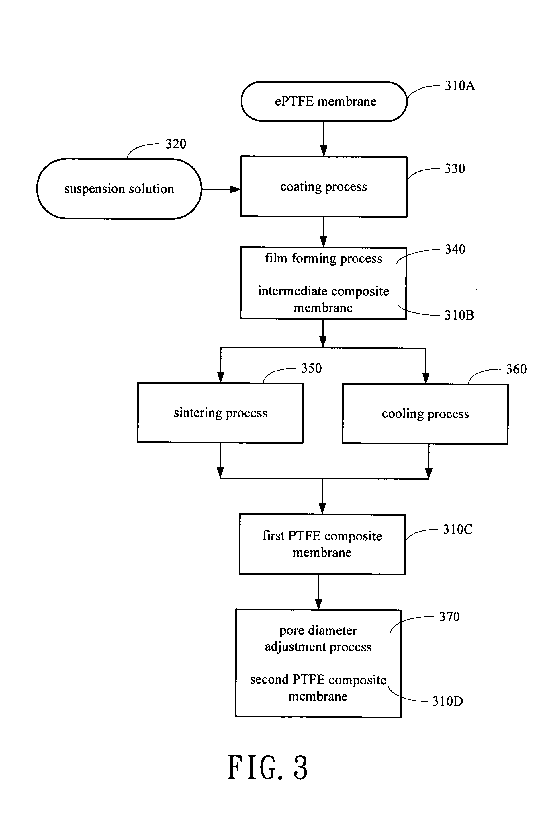
[0020] As shown in FIG. 3, the invention discloses a method for forming a composite PTFE membrane. At first, an ePTFE membrane 310A is provided that has a first surface and a second surface. A suspension solution 320 containing PTFE fine powders is provided and coated on the first surface of the ePTFE membrane 310A by a coating process 330. The coating methods, for instance, include spraying, roller coating, blade coating, dip-coating, spin-coating, etc. The suspension solution 320 containing PTFE fine powders is selected from a group consisting of the following or any combinations of the following: unsintered PTFE fine powders, thermoplastic fluorinated organic polymers, and low molecular weight PTFE. Then, a sintering process 350 is performed on the first surface of the ePTFE membrane 310A and a cooling process 360 is performed on the second surface of the ePTFE membrane 310A to form a sintered porous PTFE membrane on the first surface so as to form a first composite PTFE membrane...


PUM

PropertyMeasurementUnit
thicknessaaaaaaaaaa
pore diameteraaaaaaaaaa

Abstract

The present invention discloses discloses a composite PTFE membrane comprising an expanded PTFE membrane as substrate and a sintered porous PTFE membrane on top of it. The porous PTFE membrane on top has porous structure with interconnected channels formed with a sintering process that fuses the PTFE fine powders coated on the ePTFE membrane. Furthermore, the present invention discloses a method for forming the composite PTFE membrane.

Description

BACKGROUND OF THE INVENTION [0001] 1. Field of the Invention [0002] The present invention is generally related to composite membranes, and more particularly to composite polytetrafluoroethylene membranes. [0003] 2. Description of the Prior Art [0004] Polytetrafluoroethylene (PTFE) is a highly crystalline polymer containing two types of chemical bonds, C—C and C—F bonds. These two types of chemical bonds are strong, given the bond energy of the C—C bond about 290-335 kJ / mole and that of the C—F bond about 482 kJ / mole. Thus, PTFE has a very stable chemical property and an excellent electrical insulation property and has also low friction coefficients. In addition, PTFE can be used at 250° C. for a long period of time and is unaffected by solvent or chemical substance, when being operated below its melting point. PTFE has many applications, such as for electrical insulation, corrosion-resistance and abrasion resistance. [0005] Due to difficulty in dissolving PTFE in common solvents, tr...

Claims


Application Information

Patent Timeline
Patent Type & Authority Applications(United States)
IPC IPC(8): B32B3/00
CPCB01D67/0004B32B2457/00B01D69/12B01D71/36B01D2323/08B01D2323/28B01D2323/283B32B5/16B32B5/18B32B5/30B32B27/14B32B27/18B32B27/30B32B27/322B32B2264/0257B32B2266/025B32B2307/206B32B2307/31B32B2307/554B32B2307/714B01D67/0025Y10T428/249979Y10T428/249978Y10T428/24998Y10T428/249981
Inventor WANG, DA-MINGLEE, KUEIR-RARNLAI, JUIN-YIHHSUEH, TIEN-HSIANGLEE, YUNG-HSINLO, CHIA-HAO
Owner CHUNG YUAN CHRISTIAN UNIVERSITY
Why Eureka
Try Eureka