

Light-emitting device containing bis-phosphineoxide compound
a technology of bis-phosphineoxide and light-emitting device, which is applied in the direction of luminescent screen of discharge tube, organic compound of group 5/15, natural mineral layered products, etc., can solve the problems of low luminescent efficiency, material can be deposited, and known host materials are not suitable host materials for all dopants, and achieve low drive voltage , high luminescent efficiency
- Summary
- Abstract
- Description
- Claims
- Application Information
AI Technical Summary
Benefits of technology
Problems solved by technology
Method used
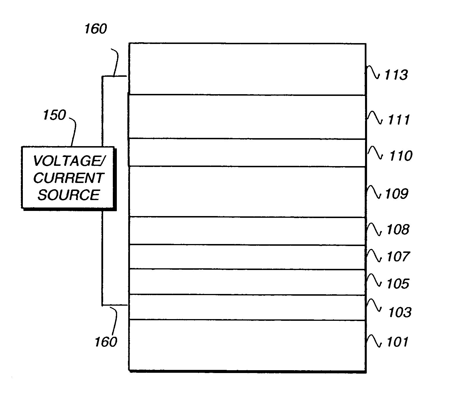
Image

Examples
synthesis example 1
Synthesis of Compound HM-1
[0107] Sodium hydride (12 mmol, in the form of a 60 wt % suspension in mineral) oil was added to a stirred solution of diphenylphosphineoxide (12 mmol) in dry N,N′-dimethylformamide (22 ml) at room temperature under nitrogen. With evolution of hydrogen a yellow solution was formed. Then, p-difluorobenzene (6 mmol) was added and the mixture was warmed to 140° C. The yellow color gradually faded and after 9 hours the product mixture was cooled and acidified with dilute hydrochloride acid. The product was extracted with chloroform, washed with sodium hydrogen carbonate and dried over magnesium sulfate. On evaporation of all chloroform the crude and almost pure product was obtained as colorless oil (90%) which after recrystallization with a dichloromethane / dimethylether mixture gave pure 1,4-phenylbis-diphenylphosphineoxide (HM-1).
synthesis example 2
Synthesis of Compound HM-2
[0108] Sodium hydride (12 mmol, in the form of a 60 wt % suspension in mineral) oil was added to a stirred solution of diphenylphosphineoxide (12 mmol) in dry N,N′-dimethylformamide (22 ml) at room temperature under nitrogen. With evolution of hydrogen a yellow solution was formed. Then, 4,4′-difluorobiphenyl (6 mmol) was added and the mixture was warmed to 140° C. The yellow color gradually faded and after 24 hours the product mixture was cooled and acidified with dilute hydrochloride acid. The product was extracted with chloroform, washed with sodium hydrogen carbonate and dried over magnesium sulfate. On evaporation of all chloroform the crude and almost pure product was obtained as colorless oil (84%) which after recrystallization with a dichloromethane / dimethylether mixture gave pure 4,4′-biphenylbis-diphenylphosphineoxide (HM-2).
synthesis example 3
Synthesis of Compound HM-3
[0109] Sodium hydride (12 mmol, in the form of a 60 wt % suspension in mineral) oil was added to a stirred solution of diphenylphosphineoxide (12 mmol) in dry N,N′-dimethylformamide (22 ml) at room temperature under nitrogen. With evolution of hydrogen a yellow solution was formed. Then, 2,6-difluoropyridine (6 mmol) was added and the mixture was stirred at room temperature. The yellow color gradually faded and after overnight the product mixture was cooled and acidified with dilute hydrochloride acid. The product was extracted with chloroform, washed with sodium hydrogen carbonate and dried over magnesium sulfate. On evaporation of all chloroform the crude and almost pure product was obtained as colorless oil (95%) which after recrystallization with a dichloromethane / dimethylether mixture gave pure 2,6-pyridylbis-diphenylphosphineoxide (HM-3).
Calculation Example
[0110] The calculated T1 values of compounds HM-1, HM-2 and HM-3 are listed in Table 1. From ...
PUM
| Property | Measurement | Unit |
|---|---|---|
| Light | aaaaa | aaaaa |
| Phosphorescence quantum yield | aaaaa | aaaaa |
| Spectrum | aaaaa | aaaaa |
Abstract
Description
Claims
Application Information