Method and test kit for the determination of iron content of in-use lubricants

a technology of in-use lubricants and test kits, which is applied in the direction of fluid controllers, instruments, laboratories, etc., can solve the problems of reducing the usable lifetime of oil, and affecting the service life of oil

Inactive Publication Date: 2006-11-30
TEXACO DEV CORP
View PDF6 Cites 23 Cited by
  • Summary
  • Abstract
  • Description
  • Claims
  • Application Information

AI Technical Summary

Problems solved by technology

Oil that is used for lubricating machines or engines, i.e., lubricant, is subject to degradation, chemical decomposition and depletion of essential additives.
Machines or engines themselves have the effect of causing a build-up of contaminant materials within the lubricant.
As the contaminant material concentration increases, the remaining usable lifetime of the oil decreases to the point where continued use of oil containing a high concentration of contaminants is detrimental to the proper operation of the machine or engine.
Conversely, changing the lubricant too early in its operational lifetime results in significant and unnecessary expense.
The nature and concentration of the contaminants may reveal faulty operator practices.
As the machines, engines, or compressors are operated, the concentration of the additives is depleted to the point where they fail to perform their inhibitory function, thus resulting in discernible increases in the amount of contaminant material existing within the lubricant.
Further, these additives may be organic and/or organo-metallic chemical compounds which, due to the operating environment and conditions of the machines, may degrade into acidic and/or basic components.
Such acidic and/or basic materials may have detrimental effects on the internal components of the machines, thereby also necessitating oil replacement.
Failure to replace lubricant that contains a high concentration of contaminant material causes damage to the machines

Method used


Image

  • Method and test kit for the determination of iron content of in-use lubricants
  • Method and test kit for the determination of iron content of in-use lubricants
  • Method and test kit for the determination of iron content of in-use lubricants

Examples


Embodiment Construction

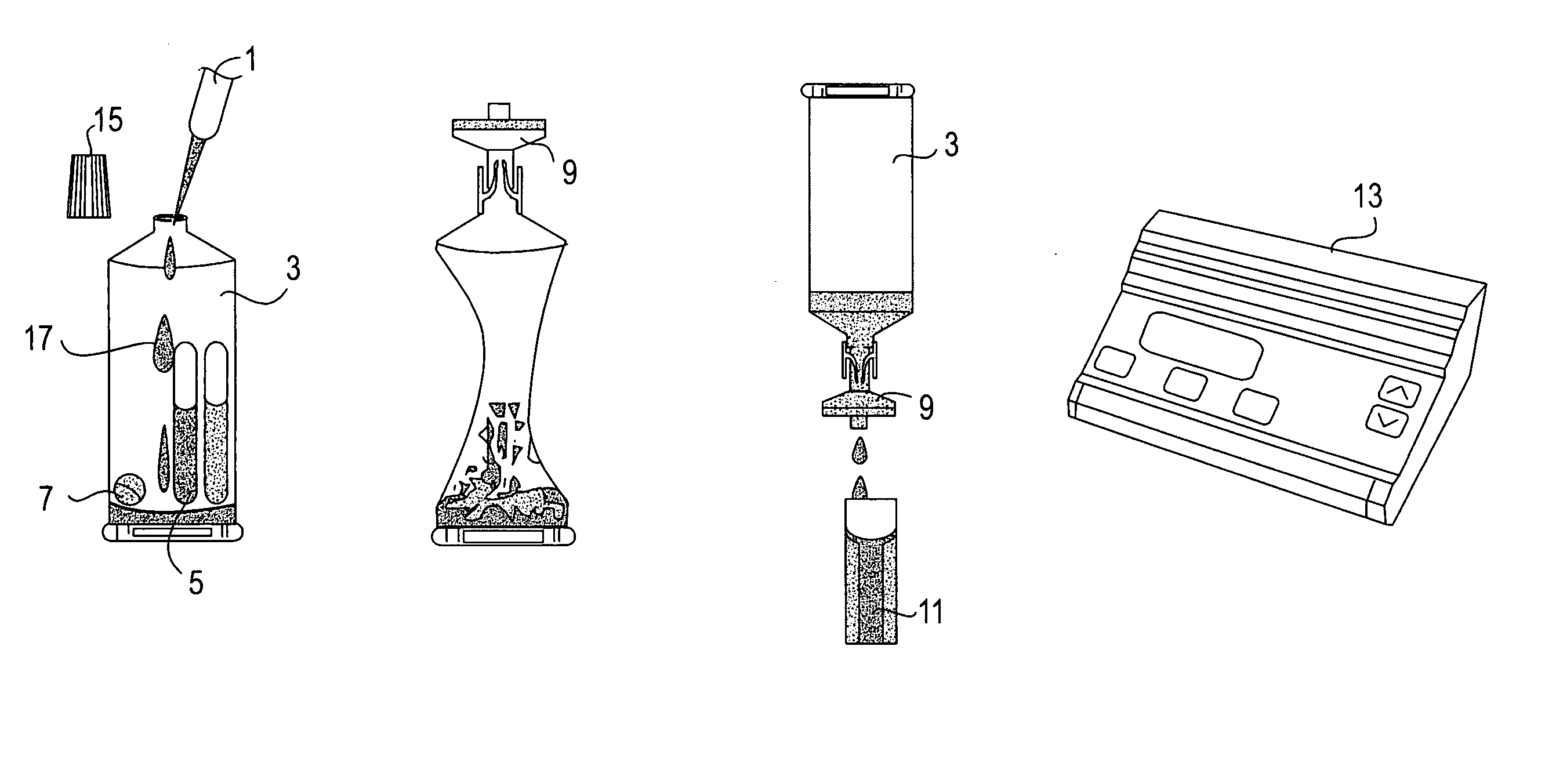
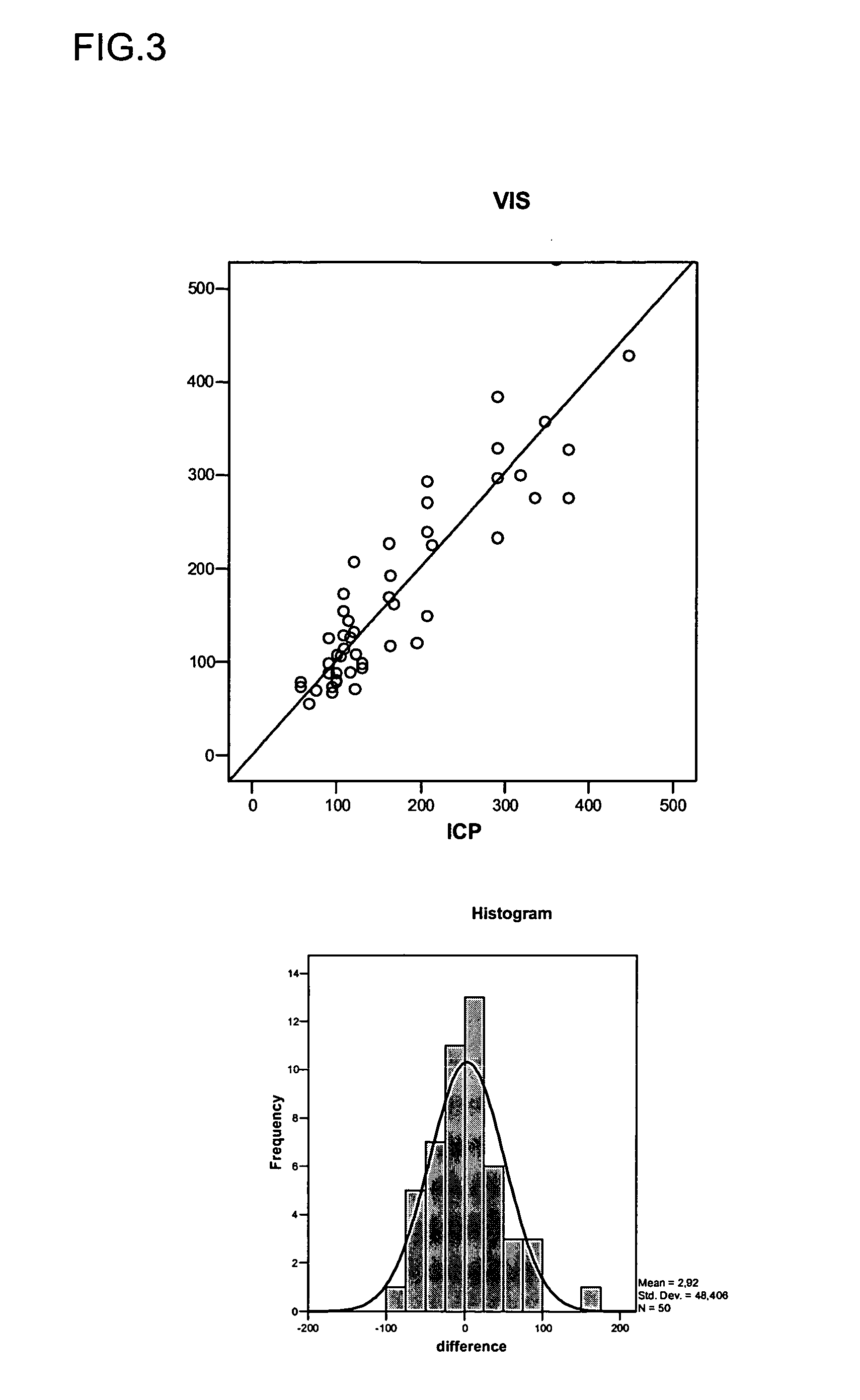
[0043] The present invention relates to a method to determine the iron content of in-use lubricants by means of visible spectroscopy and to a test kit which uses the method, which may be conducted on-site. The method of the present invention provides an accurate alternative to the standard Plasma-Atomic-Emission spectroscopic technique (ICP-AES), which must be done in a laboratory.

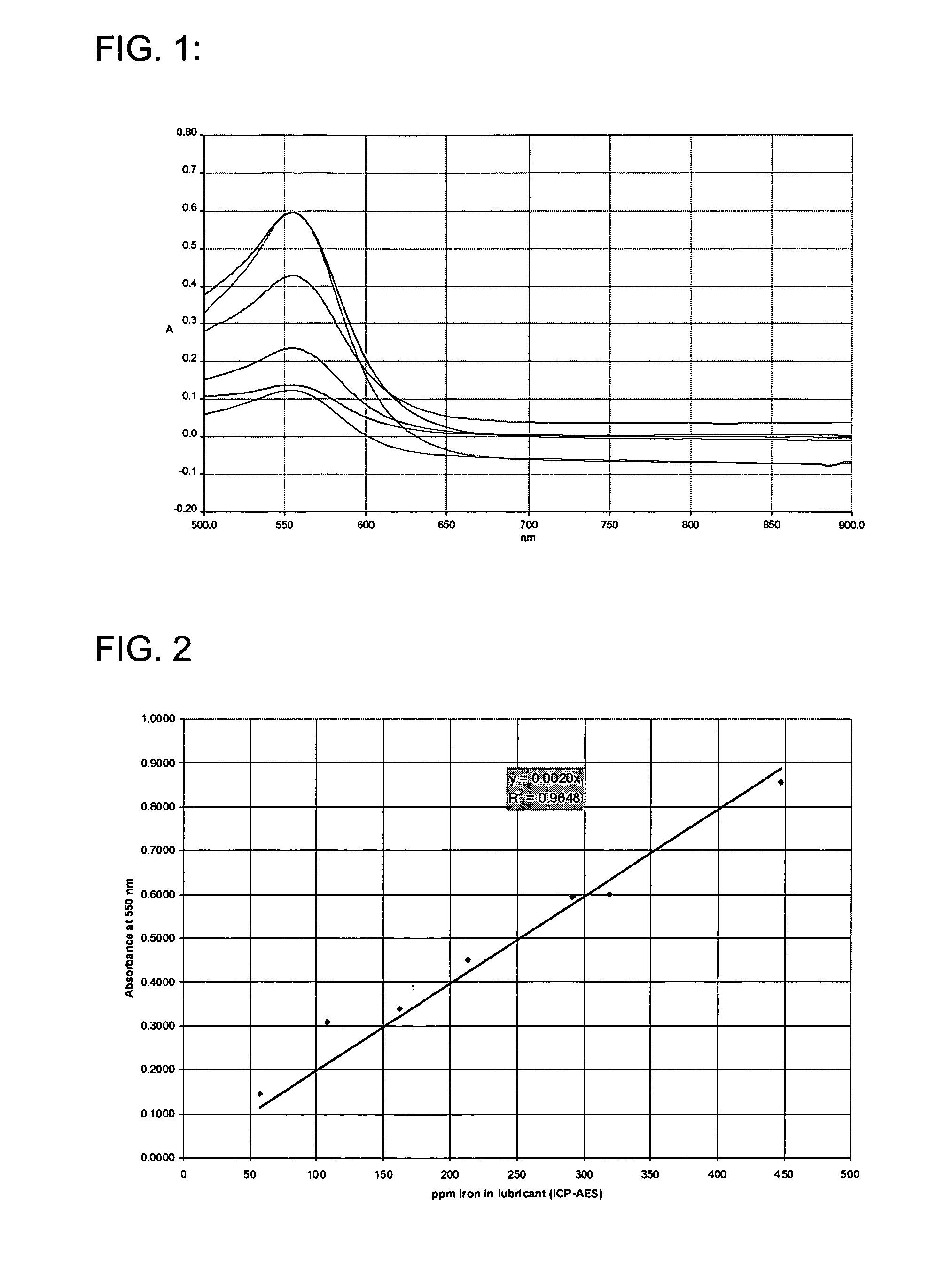
[0044] The present invention is derived from the development of a method and test kit by visible spectroscopy for the determination of the iron content of in-use lubricants, for example, cylinder drip oils. The method according to the invention gives an accurate assessment of the iron content up to 400 ppm and an indication when the iron content is above that level. The method is applicable to a great diversity of lubricants. These differ in terms of lubricant technology, Base Number (that can range up to 75 BN), and type and amount of contamination (e.g. soot, ash, metal debris, water etc.).

[0045] One a...


PUM


Abstract

Methods for determining the iron content of an in-use lubricant, which may be used on-site are disclosed. Test kits for conducting the methods are also disclosed. In one embodiment, a method according to the invention comprises: adding a predetermined amount of said in-use lubricant to an active solvent comprising predetermined amounts of an apolar organic solvent, a polar organic solvent, an organic acid, water, an iron complexing agent and a reducing agent, said active solvent having a pH between 2 and 4; thoroughly mixing the lubricant and the active solvent until the lubricant is completely dissolved; allowing the mixture to react completely and separate into a top layer and a bottom layer, the bottom layer comprising an iron complex; filtering at least a portion of the bottom layer of the mixture directly into a receptacle suitable for absorbance measurement in the visible range; photometrically measuring the net absorbance of the filtered solution at frequencies in the visible range; and converting the absorbance measurement to ppm iron content of the lubricant.

Description

FIELD OF THE INVENTION [0001] The present invention relates to a method to determine the iron content of in-use lubricants by means of visible spectroscopy and to a test kit using the method, which may be conducted on-site. The method of the present invention provides an accurate alternative to the standard Plasma-Atomic-Emission spectroscopic technique (ICP-AES), which must be done in a laboratory. One of the application areas is iron measurement of in-use lubricants having a Base Number up to 75 and being possibly contaminated even to a high extent, with soot, ash, metal debris etc. BACKGROUND OF THE INVENTION [0002] Oil that is used for lubricating machines or engines, i.e., lubricant, is subject to degradation, chemical decomposition and depletion of essential additives. Machines or engines themselves have the effect of causing a build-up of contaminant materials within the lubricant. Therefore the lubricant must be periodically monitored in order to determine its condition and ...

Claims


Application Information

Patent Timeline
IPC IPC(8): G01N33/00
CPCB01L3/502B01L3/505B01L2200/16G01N33/2858B01L2300/123B01L2400/0683G01N21/82B01L2300/0681
Inventor NAUDTS, BEATRICE I.PROOT, MARC G.
Owner TEXACO DEV CORP
Why Eureka
Try Eureka