

Electrolytic cell for producing charger anode water suitable for surface cleaning or treatment, and method for producing the same and use of the same
a technology of electrolysis cell and charger anode, which is applied in the direction of water/sewage treatment by oxidation, separation process, instruments, etc., can solve the problems of vanionic contaminants on the surface being likely to dissolve, and achieve the effects of improving surface cleaning or treatment performance, and improving the production efficiency of charged water
- Summary
- Abstract
- Description
- Claims
- Application Information
AI Technical Summary
Benefits of technology
Problems solved by technology
Method used
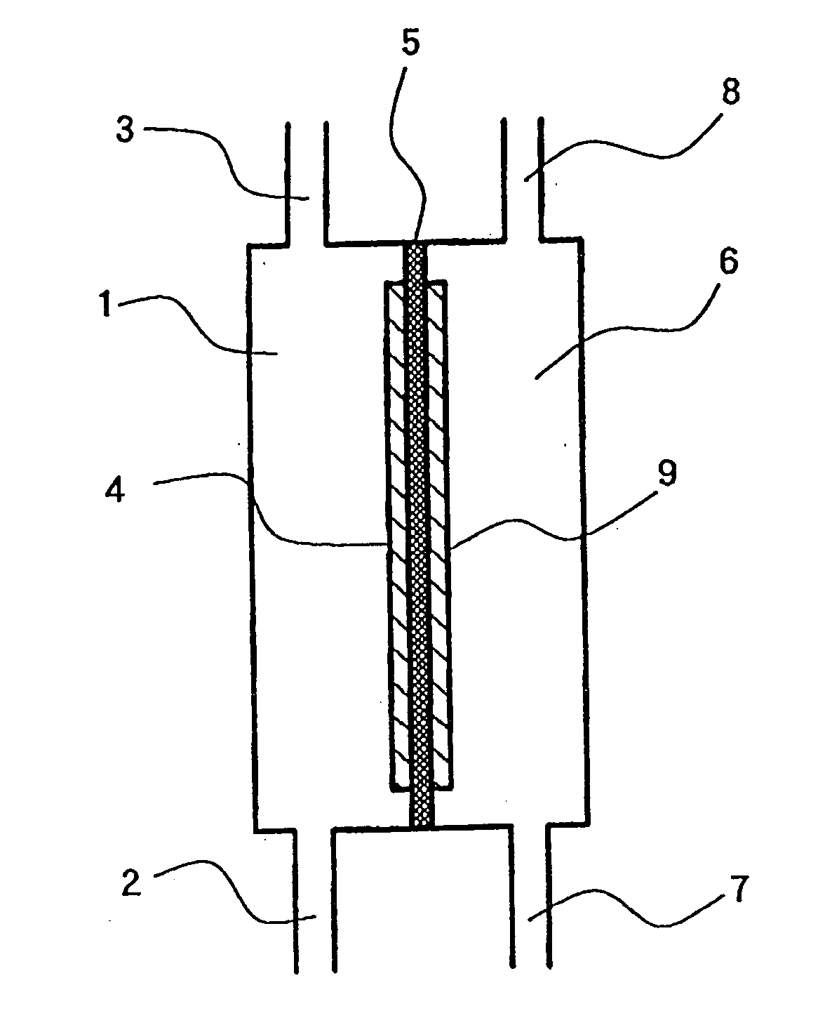
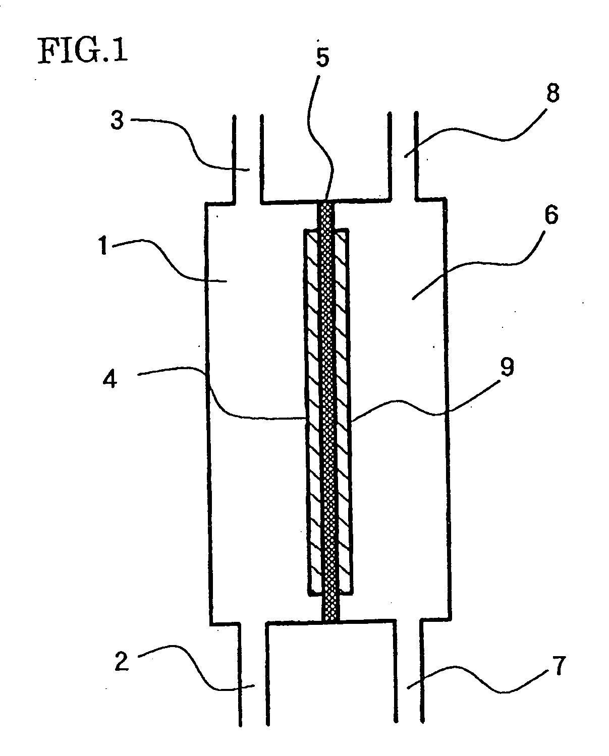
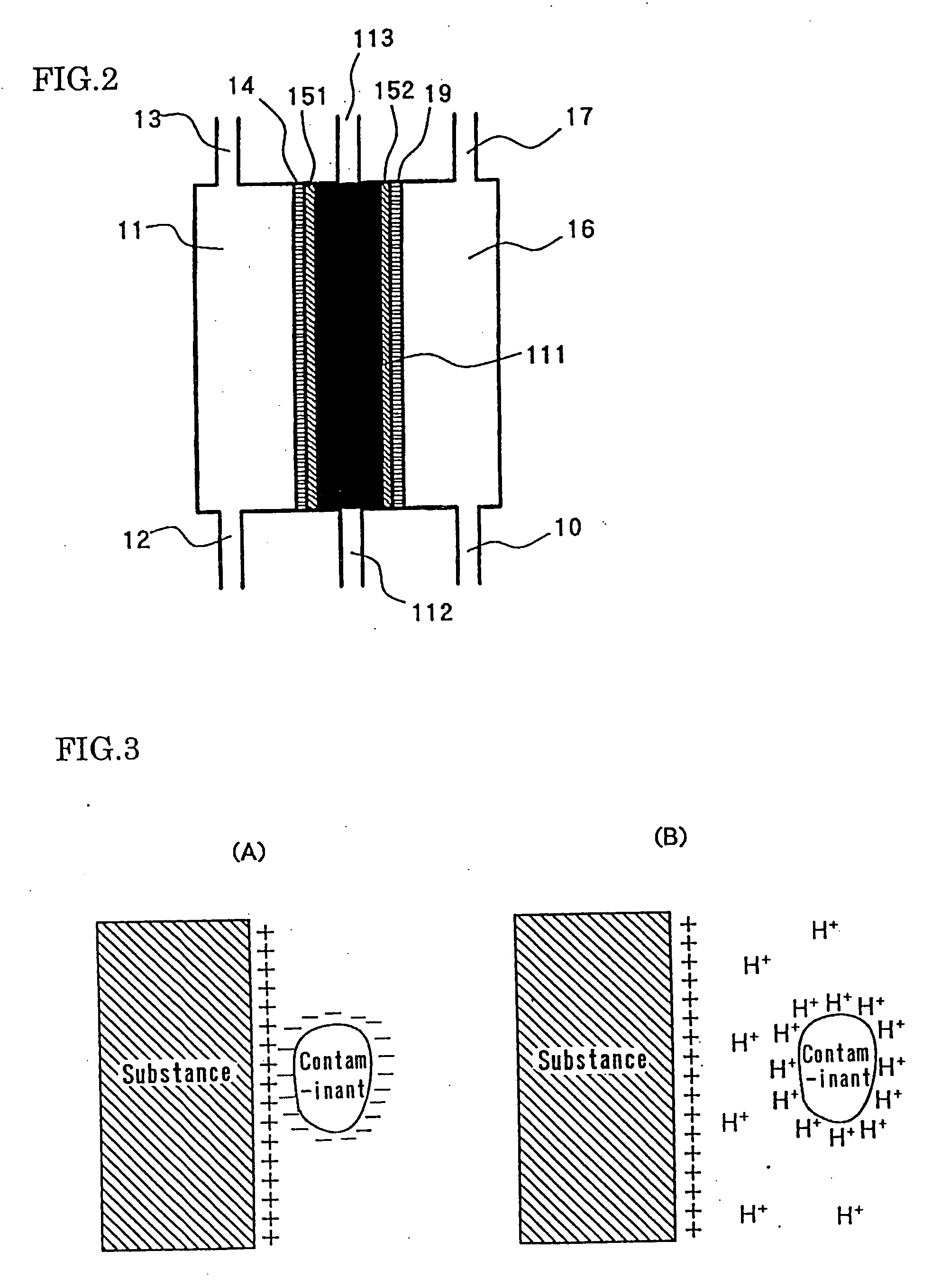
Image

Examples
example 1
[0087] The three-chamber type electrolytic cell shown in FIG. 4 was used, where ultra pure water was supplied to the inlets of the anode chamber 50, middle chamber 48 and cathode chamber 41. The ultra pure water had the following properties:
[0088] Resistivity: 18.0 MΩ / cm
[0089] Water temperature: 15° C.
[0090] Opening diameter: 4φ
[0091] Electrode: Platinum plated titanium electrode was used.
[0092] Ion-exchange membrane: The membrane 45 was made of a fluorinated cation-exchange membrane (Nafion 117 made by Du Pont).
[0093] Ion exchange resin filled in the middle chamber: The middle chamber 48 was filled with a granular fluorinated cation-exchange resin (Nafion NR50 made by Du Pont).
[0094] Ion exchange filled in the anode chamber: the room between the anode 53 and membrane 45 was also filled with NR50.
[0095] Water flow rate: ultra pure water was passed at 0.75 l / min. through the cathode chamber 41 and anode chamber 50.
[0096] The perforated anode 53 assembled in the electrolytic c...
example 2
[0102] The effects of electrolytic current on characteristics of anode water were investigated using the same electrolytic cell and ultra pure water as those used in the example 1. FIG. 8 shows the effects of electrolytic current on pH and ORP of the anode water. The charging characteristics such as pH and ORP were improved as the current density was increased.
example 3
[0103] The electrolytic cell with adjusting function of anode position shown in FIG. 6 was used to investigate the relationship between the anode electrode position and the charging characteristics such as pH and ORP of anode water, where apparent electrolytic current was set at 4 A. FIG. 9 indicates the result.
[0104] The minus position of anode in FIG. 9 indicates that the anode approached towards the cathode side. In order set the electrolytic current at a given level, the electrolytic voltage was decreased, as the anode position was moved toward the cathode side. As the position of anode was moved toward the counter side, the charging characteristics such as pH and ORP were improved. These results show that the effective contact area between the cation exchange resins and anode decreases as the anode is move towards the counter side. The fluorinated ion exchange resin used in the example 3 had rubber like elasticity and was capable of reversibly changing the charging characteris...
PUM
| Property | Measurement | Unit |
|---|---|---|
| reduction potential | aaaaa | aaaaa |
| reduction potential | aaaaa | aaaaa |
| temperature | aaaaa | aaaaa |
Abstract
Description
Claims
Application Information