High performance kinetic spray nozzle

a kinetic spray and nozzle technology, applied in the direction of furnaces, heat treatment equipment, manufacturing tools, etc., can solve the problems of limiting the flow of heated gas within the kinetic spray system, the difficulty of accelerating larger powder particles, and the inability to achieve the velocity of heated gas, so as to increase the overall length of the nozzle assembly, avoid any negative effects, and increase the amount of time a stream

Inactive Publication Date: 2006-12-07
F W GARTNER THERMAL SPRAYING
View PDF11 Cites 63 Cited by
  • Summary
  • Abstract
  • Description
  • Claims
  • Application Information

AI Technical Summary

Benefits of technology

[0009] The subject invention also provides a method of coating a substrate with a powder applied by the kinetic spray system. The method comprises the steps of mixing the powder with a flow of heated gas; directing the flow of heated gas through the convergent portion, the throat portion, and the divergent portion of the nozzle assembly to accelerate the flow of heated gas and provide a drag force to act upon the powder to accelerate the powder; and passing the accelerated flow of heated gas and the powder through the extension portion of the nozzle assembly to provide additional time for the drag force of the flow of heated gas to act upon the powder to further accelerate the powder to a critical velocity.
[0010] Accordingly, the subject invention increases the ove

Problems solved by technology

Additionally, it is more difficult to accelerate larger powder particles.
However, there is a

Method used


Image

  • High performance kinetic spray nozzle
  • High performance kinetic spray nozzle
  • High performance kinetic spray nozzle

Examples


Embodiment Construction

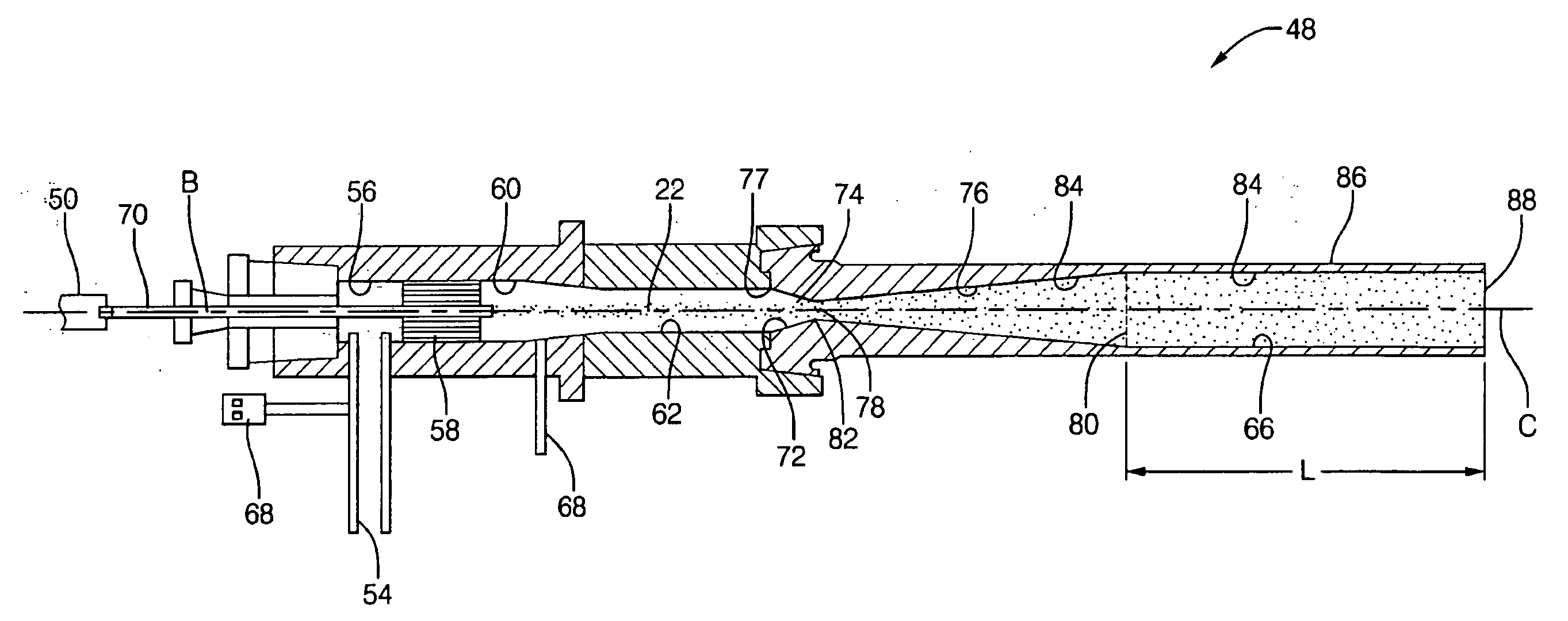
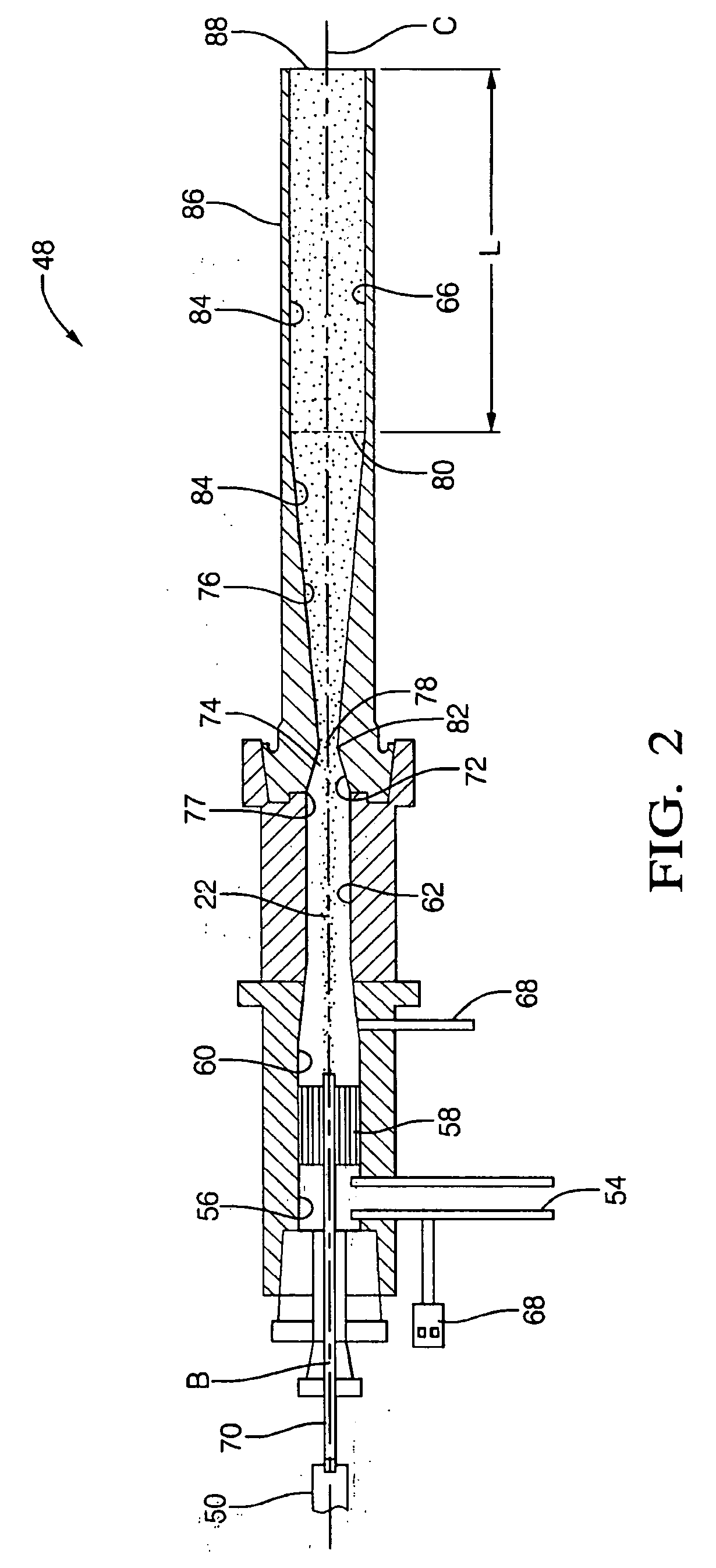
[0021] The present invention comprises an improvement to the kinetic spray system and nozzle assembly 20 as generally described in U.S. patent application Ser. No. 2005 / 0214474 A1; U.S. Pat. Nos. 6,139,913 and 6,283,386; and the article by Van Steenkiste, et al. entitled “Kinetic Spray Coatings” published in Surface and Coatings Technology Volume III, Pages 62-72, Jan. 10, 1999. The disclosures of which are all herein incorporated by reference.

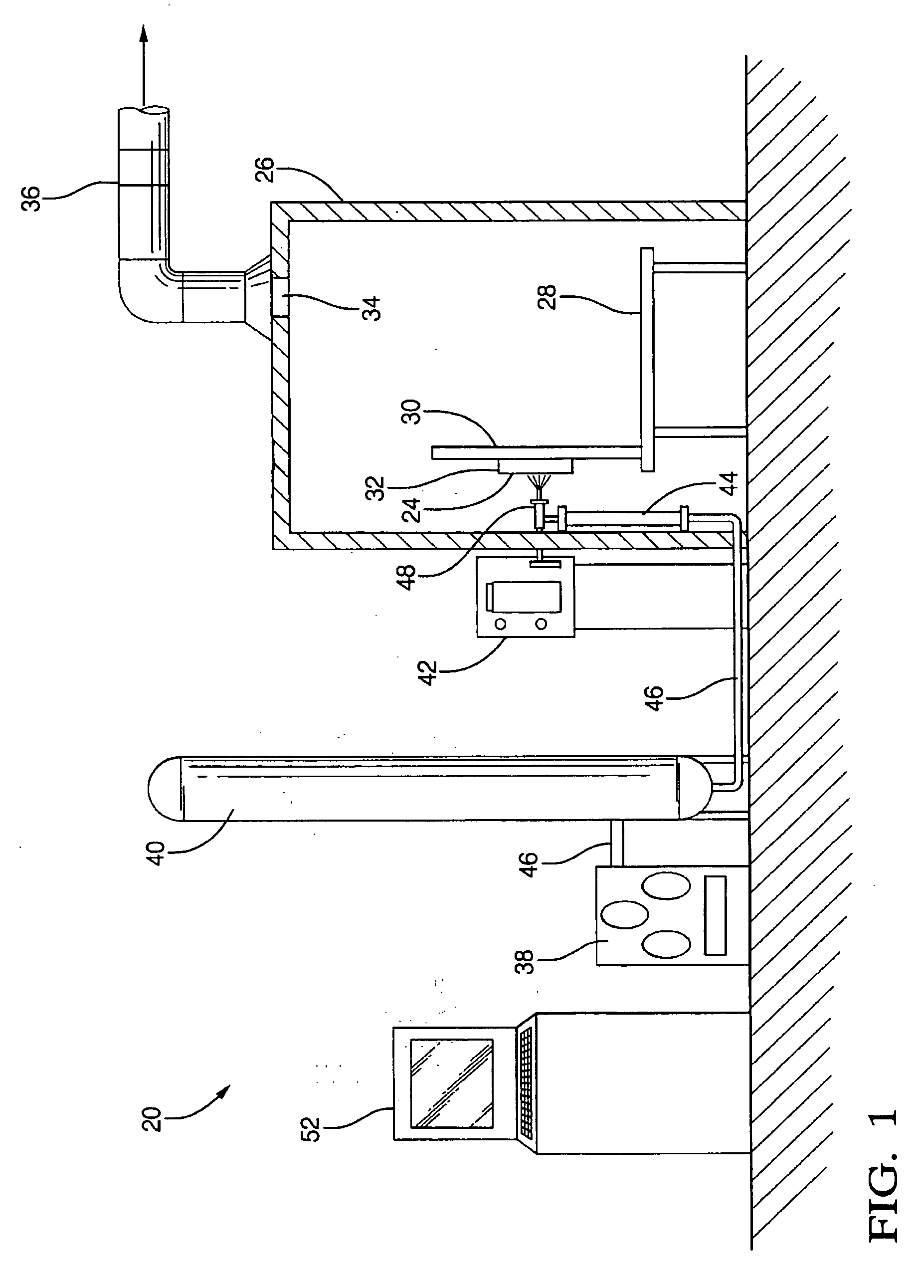
[0022] Referring to the Figures, wherein like numerals indicate corresponding parts throughout the several views, a kinetic spray system is generally shown at 20. Referring to FIG. 1, the kinetic spray system 20 applies a coating of powder particles 22 to a substrate material 24. A flow of heated gas suspends the powder particles 22, which are then sprayed onto the substrate 24 at high velocities. As disclosed in U.S. Pat. No. 6,139,913 the substrate material 24 may be comprised of any of a wide variety of materials including a metal, an allo...


PUM

PropertyMeasurementUnit
Lengthaaaaaaaaaa
Lengthaaaaaaaaaa
Lengthaaaaaaaaaa

Abstract

A nozzle assembly for a kinetic spray system includes a convergent portion, a throat portion, and a divergent portion, each cooperating together to define a passage therethrough for passing a mixture of powder particles suspended in a flow of a high pressure heated gas. The nozzle assembly further includes an extension portion attached to the divergent portion and extending to a distal end a pre-determined length from the divergent portion of the nozzle assembly. The extension portion permits a dragging force exerted on the powder particles by the flow of high pressure heated gas to act upon the powder particles for a longer duration of time, thereby permitting the powder particles to accelerate to a greater velocity than has been previously achievable.

Description

[0001] This application is a continuation-in-part of U.S. Ser. No. 10 / 924270 filed Aug. 23, 2004BACKGROUND OF THE INVENTION [0002] 1. Field of the Invention [0003] The subject invention generally relates to a nozzle assembly for a kinetic spray system. [0004] 2. Description of the Related Art [0005] A nozzle assembly for a kinetic spray system typically comprises a mixing chamber for mixing a stream of powder particles under positive pressure with a flow of a heated gas. The mixing chamber is connected to a converging diverging deLaval type supersonic nozzle. The heated gas is also introduced into the mixing chamber under a positive pressure, which is set lower than the positive pressure of the stream of powder particles. In the mixing chamber, the flow of heated gas and the stream of powder particles mix together to form a gas / powder mixture. The gas powder mixture flows from the mixing chamber into the supersonic nozzle, where the powder particles are accelerated to a velocity bet...

Claims


Application Information

Patent Timeline
IPC IPC(8): C21D1/00B05D1/08C21D1/62B05C5/00
CPCB05B1/044C23C24/04B05B7/1613B05B7/1486B05B1/02B05B1/26
Inventor ZHAO, ZHIBOGILLISPIE, BRYAN A.HAN, TAEYOUNGELMOURSI, ALAA A.PATEL, NILESH B.
Owner F W GARTNER THERMAL SPRAYING
Why Eureka
Try Eureka