Self restrained fitting for PVC and ductile iron pipe

a technology of ductile iron pipe and self-restraint fitting, which is applied in the direction of hose connection, coupling, manufacturing tools, etc., can solve the problems of utilizing a cumbersome external mechanical restraint system, and achieve the effect of not easily bent or flexed

Inactive Publication Date: 2006-12-14
S & B TECHN PRODS
View PDF15 Cites 10 Cited by
  • Summary
  • Abstract
  • Description
  • Claims
  • Application Information

AI Technical Summary

Benefits of technology

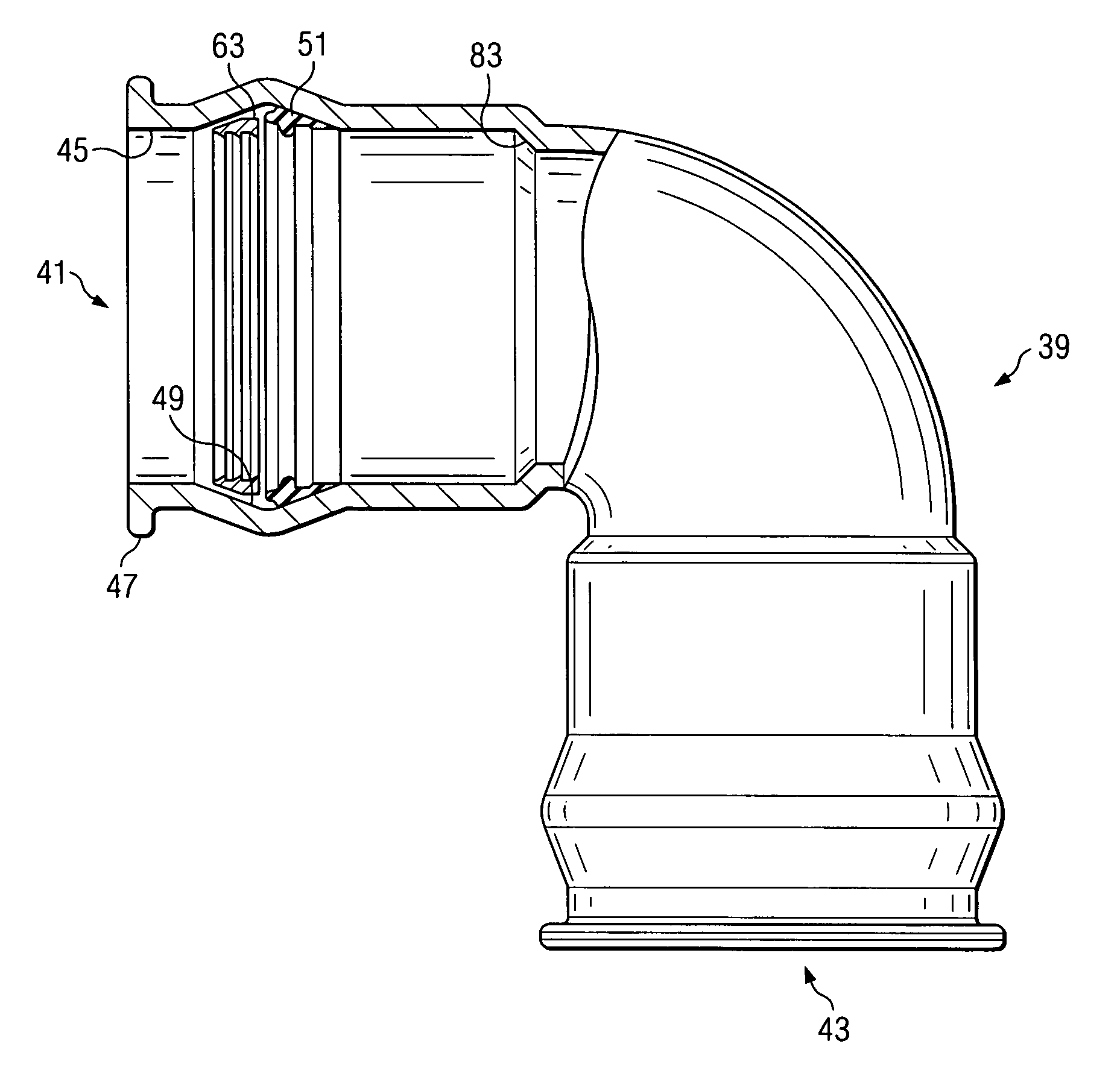
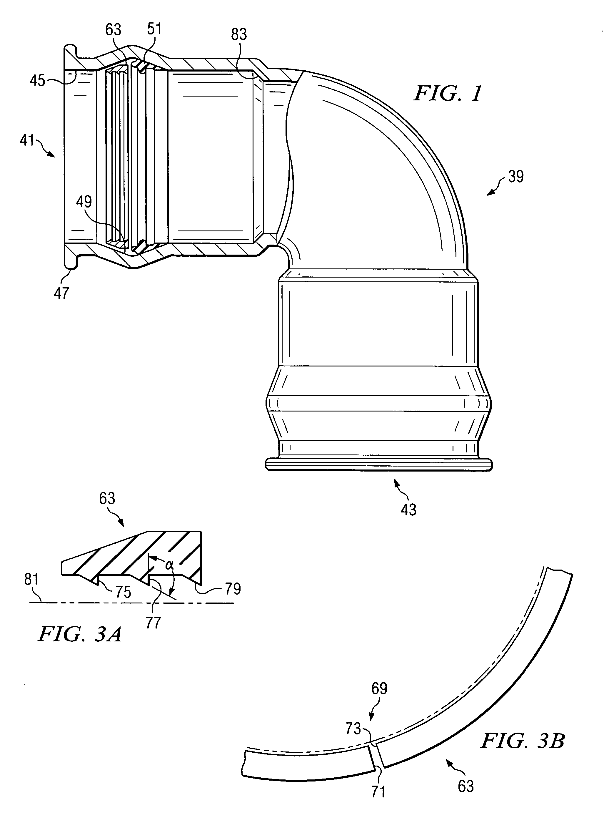
[0017] The mating male pipe can be formed of any number of convenient materials including plastics, such as PVC, polyethylene and other polyolefins, as well as from steel, iron, alloys or other cast ferrous materials. The sealing ring can be a Rieber style sealing gasket of the type normally installed on a belling mandrel and belled over in a plastic pipe bell manufacturing operation. The sealing ring can also be a snap-fit gasket having an embedded reinforcing ring which is not easily bent or flexed by hand and which is initially of a diameter which is generally greater than the diameter of the mouth opening of the as-cast fitting. In the case where the mating male pipe section is formed of iron, the gripping ring is preferably formed of hardened steel which has been heat treated to at least about 370 Brinell hardness (BHN) so that the teeth of the ring can penetrate the mating male iron pipe exterior surface or form a buttress on the pipe surface. Where the mating male pipe is formed of plastic or polyolefin materials, it is not generally necessary to heat treat the gripping ring. The teeth on the gripping ring are oriented so that they allow the mating male pipe to be inserted in the end opening of the as-cast fitting and moved in a first longitudinal direction to make up a secure joint. However, the orientation of the teeth restrains movement of the mating male pipe section in an opposite, longitudinal direction.

Problems solved by technology

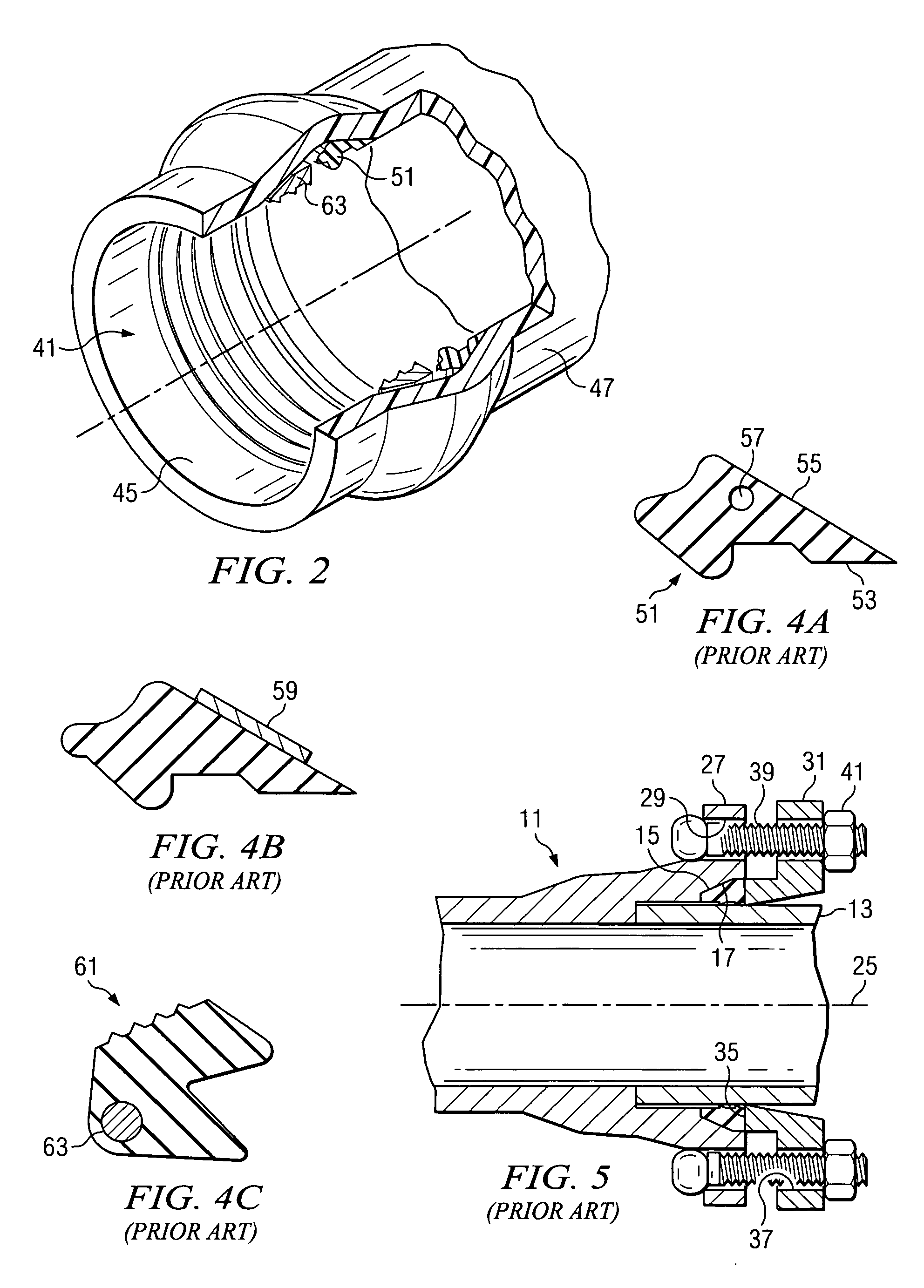
Instead, it was necessary to utilize a cumbersome external mechanical restraint system made up of the flange, bolts, screws, etc., as discussed above.

Method used


Image

  • Self restrained fitting for PVC and ductile iron pipe
  • Self restrained fitting for PVC and ductile iron pipe
  • Self restrained fitting for PVC and ductile iron pipe

Examples


Embodiment Construction

[0028] The present invention deals with piping systems of the type used in water, sewage and other municipal fluid conveyance systems. In the past, such pipelines were traditionally formed of a ferrous metal. By “ferrous metal” is meant iron and alloys of iron. For example, one type of ferrous metal which is commonly encountered in the water works industry is “ductile iron.” This particular type of metal is widely used because it offers a combination of a wide range of high strength, wear resistance, fatigue resistance, toughness and ductility in addition to the well-known advantages of cast iron-castability, machinability, damping properties and economy of production. It takes its name from the fact that it is “ductile” in nature, rather than being brittle, as was the case with earlier cast iron products and materials. Today, grades of ductile iron are available offering the option of choosing high ductility with grades guaranteeing more than 18% elongation, or high strength, with ...


PUM

PropertyMeasurementUnit
Brinell hardnessaaaaaaaaaa
tensile strengthsaaaaaaaaaa
elongationaaaaaaaaaa

Abstract

A combination sealing and restraint system for an as-cast ductile iron fitting is shown for both sealing and preventing separation of an iron pipe fitting and a mating male pipe. The restraint system includes both a sealing ring and a combination gripping ring which are installed in a groove provided in a mouth region of the iron fitting. The gripping ring has teeth on an inner surface which are initially angled away from an outer surface of the male pipe. The teeth are forced into engagement with the exterior surface of the mating male pipe as the pipe joint at the fitting is assembled. The teeth are oriented to allow movement of the male pipe in a first direction relative to an end opening of the fitting during assembly, but to resist movement in a opposite direction after the fitting joint has been assembled. The sealing ring and gripping ring are installed in the annular groove of the as-cast iron fitting after the iron casting operation at the factory.

Description

CROSS-REFERENCE TO RELATED APPLICATIONS [0001] The present application contains subject matter which is related to Applicant's prior U.S. application, Ser. No. 11 / 070,554, filed Mar. 2, 2005, entitled “Restraining Mechanical Joint Gasket For Ductile Iron Pipe”, by the same inventors, presently pending.BACKGROUND OF THE INVENTION [0002] 1. Field of the Invention [0003] The present invention relates generally to the field of pipe connections and to devices used in the pipeline construction industry. More particularly, this invention relates to a combination sealing and restraint system for use in “as-cast” ductile iron pipe fittings. [0004] 2. Description of the Prior Art [0005] Pipes are commonly used for the conveyance of fluids under pressure, as in city water lines. They may also be used as free-flowing conduits running partly full, as in drains and sewers. Pipes for conveying water in appreciable quantities have been made of steel, cast iron, concrete, vitrified clay, and most re...

Claims


Application Information

Patent Timeline
Patent Type & Authority Applications(United States)
IPC IPC(8): F16L33/16
CPCF16L37/0925Y10T29/49936Y10T29/49945
Inventor JONES, JIMCORBETT, BRADFORD G. JR.
Owner S & B TECHN PRODS
Why Eureka
Try Eureka