Spiral waveguide slow wave resonator structure

a spiral waveguide and slow wave technology, applied in the field of optical resonators, can solve the problems of high loss, difficult extension of multipoles, inefficient, etc., and achieve the effect of slow light propagation

Inactive Publication Date: 2006-12-14
HARRIS CORP
View PDF20 Cites 5 Cited by
  • Summary
  • Abstract
  • Description
  • Claims
  • Application Information

AI Technical Summary

Benefits of technology

[0022] In view of the foregoing background, it is therefore an object of the present invention to provide an optical microresonator formed as a microcylinder having a resonant waveguide that can slow light propagating along the microcylinder.
[0023] This and other objects, features and advantages in accordance with the present invention are provide by a resonant waveguide on a microcylinder. Whispering gallery modes on the microcylinder using a circumferential spiral or one-dimensional beam propagation coating and an effective index profile can account for the cylindrical geometry and provide a novel, unobvious, homogenous, waveguide structure. The present invention extends to complex, coupled structures. The microcylinder includes resonators, such as a ridge, forming a spiral resonant waveguide and can be fabricated by an ultraviolet laser that writes on a rotating photoresist-coated microcylinder as one non-limiting example, allowing a more simple fabrication technique than used with microspheres for compound (multipole) structures.

Problems solved by technology

Fabry-Perot structures have been widely used for many applications, but have difficult extensions to the multipole.
One drawback is their high losses.
They are not efficient, however, for some applications requiring an extension to multipole filters.
These ultra-high “Q” factor and small mode volume results in high circulating intensities because of the cavity build-up factor.
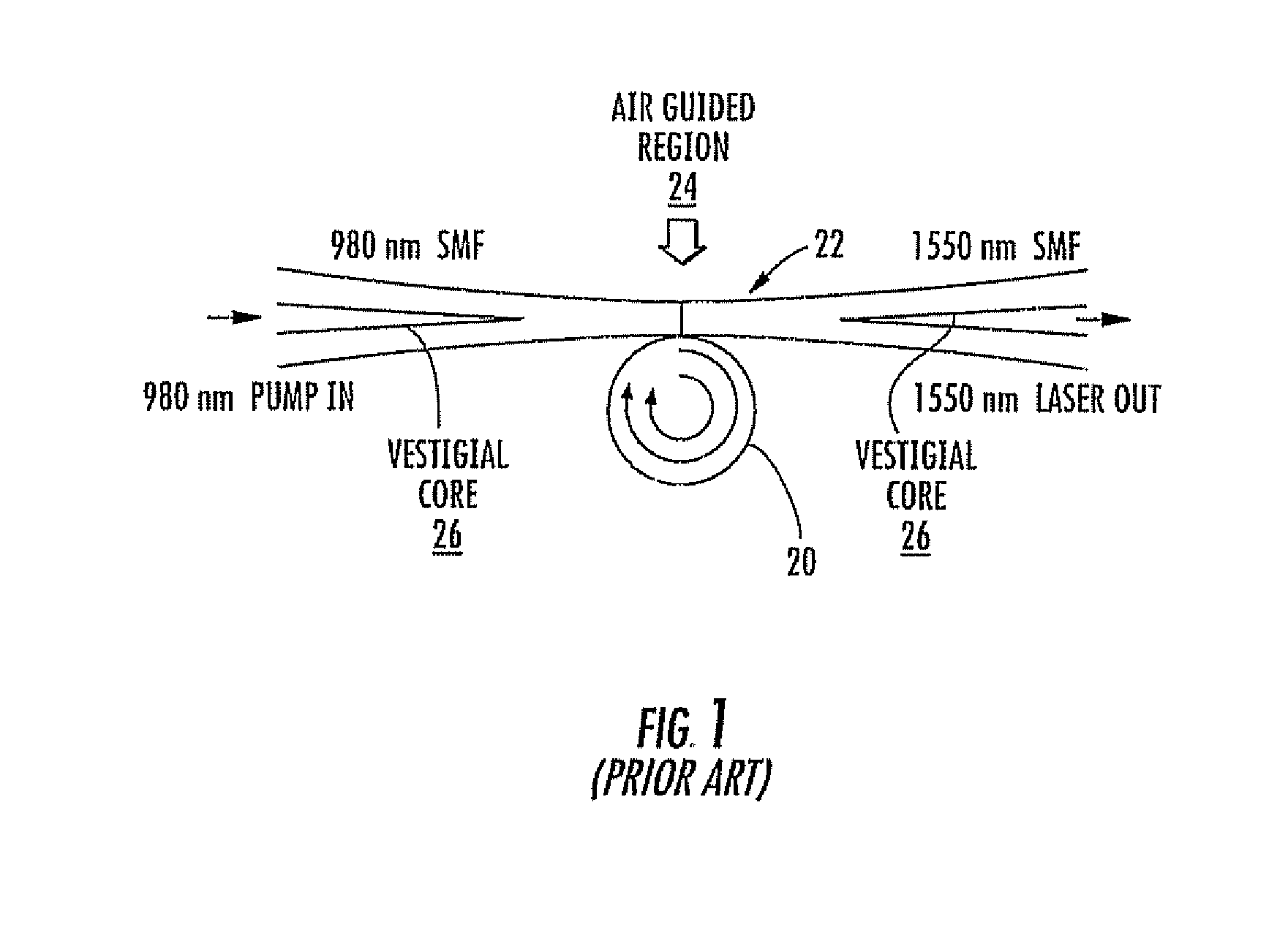
Although spherical resonators, waveguide ring resonators, Fabry-Perot structures and toroid microcavities have been advantageously used as indicated above, these devices still have limitations when optical fibers are coupled, even though these devices often are easily fabricated.
Although the optical resonator can provide some coupling, it is limited in its use and may not provide adequate coupling for input / output functions.
Its manufacturing requires non-rotating upper and lower capillary tubes to hold a spinning optical fiber, which may not ensure accuracy and have excess tolerance.
It also does not address polarization issues, slower waveguide structures, multiple node contacts, and the use of coatings for imparting waveguide resonance or similar issues.

Method used


Image

  • Spiral waveguide slow wave resonator structure
  • Spiral waveguide slow wave resonator structure
  • Spiral waveguide slow wave resonator structure

Examples


Embodiment Construction

[0058] The present invention will now be described more fully hereinafter with reference to the accompanying drawings, in which preferred embodiments of the invention are shown. This invention may, however, be embodied in many different forms and should not be construed as limited to the embodiments set forth herein. Rather, these embodiments are provided so that this disclosure will be thorough and complete, and will fully convey the scope of the invention to those skilled in the art. Like numbers refer to like elements throughout, and prime notation is used to indicate similar elements in alternative embodiments.

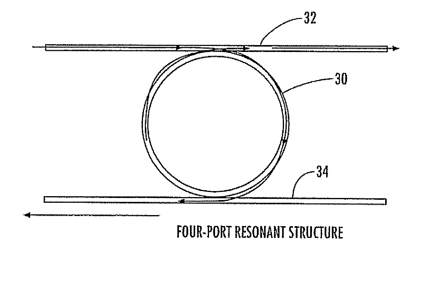
[0059] The present invention is advantageous over prior art spherical resonators, waveguide ring resonators and Fabry-Perot structures, including toroid microcavities, and simple cylindrical resonators as described in the incorporated by reference '730 published patent application. The present invention is directed to an optical microresonator that includes a resonant wav...


PUM


Abstract

An optical microresonator includes microcylinder and spiral resonant waveguide formed on the microcylinder that optically couples light from an optical source waveguide to the microcylinder and slows light propagating along the microcylinder. A coupling element, for example, a diffraction grating can be operative with the resonant waveguide structure and configured to meet a desired phase matching. A second microcylinder having a spiral resonant waveguide formed thereon can be positioned adjacent to the spiral resonant waveguide formed on the first microcylinder for coupling therewith. The spiral resonant waveguides on first and second microcylinders can be configured for slowing light propagating along the microcylinder.

Description

FIELD OF THE INVENTION [0001] The present invention relates to the field of optical resonators, and more particularly, to optical microresonators that exhibit whispering gallery modes. BACKGROUND OF THE INVENTION [0002] Telecommunications systems incorporate extensive optical fiber networks using frequency multiplexing / demultiplexing techniques for optical communications signals. These types of optical communications systems require add / drop filters for selecting a single wavelength from complex optical signals that are typically frequency multiplexed together. Also, optical sensors are used at narrow band frequencies and wavelengths and may require add / drop or other functionality. These sensors are required for accelerometers, chemical and biological sensors, and similar applications. [0003] Prior art devices for these add / drop filters and optical sensors include Fabry-Perot structures, waveguide ring resonators, and spherical resonators. Fabry-Perot structures have been widely use...

Claims


Application Information

Patent Timeline
Patent Type & Authority Applications(United States)
IPC IPC(8): G02B6/26G02B6/42
CPCG02B6/10G02B6/12002G02B6/12007G02B6/29395G02B6/29343G02B6/29359G02B6/29341
Inventor MONTGOMERY, ROBERT M.LANGE, MICHAEL R.DEROY, MICHAEL
Owner HARRIS CORP
Why Eureka
Try Eureka