Semiconductor device fabrication method

a technology of semiconductor devices and fabrication methods, applied in the direction of semiconductor devices, transistors, electrical equipment, etc., can solve the problems of increasing junction leak current, and insufficient so as to improve the operation speed of pmos transistors, reduce the resistance of sheets, and suppress junction leak current

Active Publication Date: 2006-12-14
FUJITSU LTD
View PDF5 Cites 69 Cited by
  • Summary
  • Abstract
  • Description
  • Claims
  • Application Information

AI Technical Summary

Benefits of technology

[0026] According to the present invention, the amorphous layer is formed on the silicon germanium layer, and thus formed amorphous layer is reacted with the nickel film to thereby form the nickel silicide film. Because of no crystal boundaries in the amorphous layer to react with the nickel film, the silicidation homogeneously goes on. The silicidation, which homogeneously goes on, can prevent the generation of region where the nickel silicide is absent, on the silicon germanium layer. Because of no crystal faces in the amorphous layer, the Ni(Si1-xGex)2 crystals are prevented from being formed in spikes. Thus, according to the present invention, even when the silicon germanium layer is silicided by using a thin nickel film, the sheet resistance can be low, and the junction leak current can be suppressed. Furthermore, according to the present invention, compression strain is applied to the channel region by the silicon germanium layer buried in the source / drain diffused region, whereby the operation speed of PMOS transistors can be improved. Thus, the present invention can provide a semiconductor device having good electric characteristics.

Problems solved by technology

When PMOS transistors are simply formed, often the PMOS transistors cannot have sufficiently high operation speed.
When the silicide film is formed thick, the electric field between the junctions of the source / drain diffused layer and the silicide film becomes stronger, which increases the junction leak current.
When thin nickel film is simply used to silicide the silicon germanium layer, Ni(Si1-xGex)2 crystals are formed in spikes below the silicide film down to the vicinity of the junctions of the source / drain diffused layer, which often increases the junction leak current.

Method used


Image

  • Semiconductor device fabrication method
  • Semiconductor device fabrication method
  • Semiconductor device fabrication method

Examples


first embodiment

A FIRST EMBODIMENT

[0109] The semiconductor device according to a first embodiment of the present invention and the method for fabricating the semiconductor device will be explained with reference to FIGS. 10 to 24. FIG. 10 is a sectional view of the semiconductor device according to the present embodiment, which illustrates a structure thereof.

[0110] (The Semiconductor Device)

[0111] First, the structure of the semiconductor device according to the present embodiment will be explained with reference to FIG. 10.

[0112] In FIG. 10, an NMOS transistor-to-be-formed region 96 is illustrated on the left side of the drawing, and on the right side of the drawing, a PMOS transistor-to-be-formed region 98 is illustrated.

[0113] Device isolation regions 46 for defining device regions are formed in a silicon substrate 34. Wells (not illustrated) are formed in the silicon substrate 34 with the device isolation regions 46 formed in.

[0114] In the NMOS transistor-to-be-formed region 96, on the si...

second embodiment

A SECOND EMBODIMENT

[0222] The semiconductor device fabrication method according to a second embodiment of the present invention will be explained with reference to FIGS. 25A to 28. FIGS. 25A to 28 are sectional views of the semiconductor device according to the present embodiment in the steps of the method for fabricating the semiconductor device. The same members of the present embodiment as those of the method for fabricating the semiconductor according to the first embodiment are represented by the same reference numbers not to repeat or to simplify their explanation.

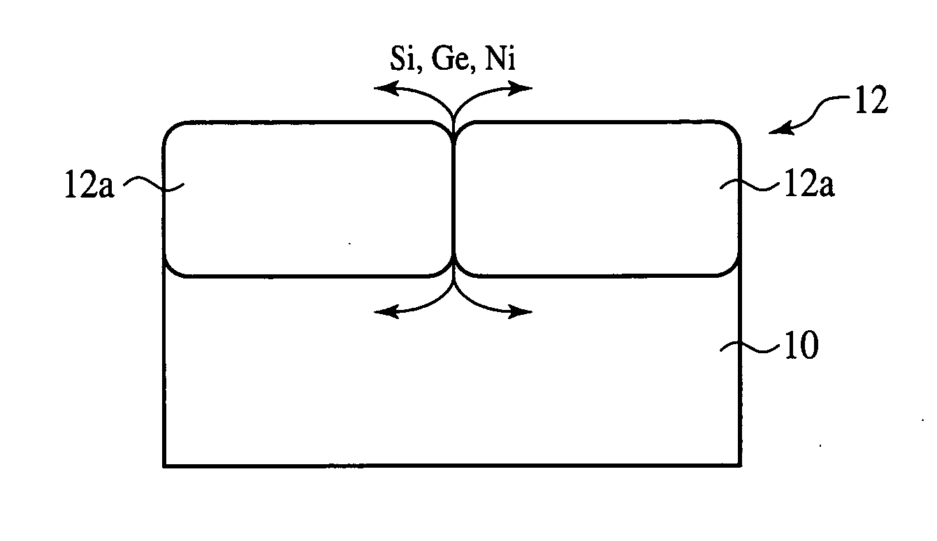
[0223] The method for fabricating the semiconductor device according to the present embodiment is characterized mainly in that an amorphous layer is formed by depositing the amorphous layer selectively on a silicon germanium layer, and the amorphous layer is silicided by using a nickel film.

[0224] First, the steps up to the step of forming a recess 104 in the source / drain diffused layer 64p including the recess for...

third embodiment

A THIRD EMBODIMENT

[0233] The semiconductor device fabrication method according to a third embodiment of the present invention will be explained with reference to FIGS. 29A to 32. FIGS. 29A to 32 are sectional views of the semiconductor device according to the present embodiment in the steps of the method for fabricating the semiconductor device, which illustrate the method. The same members of the present embodiment as those of the method for fabricating the semiconductor device according to the first or the second embodiment are represented by the same reference numbers not to repeat to simplify their explanation.

[0234] The semiconductor device fabrication method according to the present embodiment is characterized mainly in that an amorphous layer is deposited on the entire surface, and the amorphous layer is patterned to form the amorphous layer on a silicon germanium layer, and such amorphous layer is silicided by using a nickel film.

[0235] First, the steps up to the step of f...


PUM


Abstract

The semiconductor device fabrication method comprising the step of forming a gate electrode 54p on a semiconductor substrate 34; the step of forming a source/drain diffused layer 64p in the semiconductor substrate 34 on both sides of the gate electrode 54p; the step of burying a silicon germanium layer 100b in the source/drain diffused layer 64p; the step of forming an amorphous layer at an upper part of the silicon germanium layer 101; the step of forming a nickel film 66 on the amorphous layer 101; and the step of making thermal processing to react the nickel film 66 and the amorphous layer 101 with each other to form a silicide film 102b on the silicon germanium layer 100b. Because of no crystal boundaries in the amorphous layer 101 to react with the nickel film 66, the silicidation homogeneously goes on. Because of no crystal faces in the amorphous layer 101, the Ni(Si1-xGex)2 crystals are prevented from being formed in spikes. Thus, even when the silicon germanium layer 100b is silicided by using a thin nickel film 66, the sheet resistance can be low, and the junction leak current can be suppressed.

Description

CROSS-REFERENCE TO RELATED APPLICATION [0001] This application is based upon and claims priority of Japanese Patent Application No. 2005-172035, filed on Jun. 13, 2005, the contents being incorporated herein by reference. BACKGROUND OF THE INVENTION [0002] The present invention relates to a semiconductor device fabrication method, more specifically a semiconductor device fabrication method in which silicidation is made by using nickel. [0003] As a technique for making gate electrodes and source / drain diffused layers low resistive, the so-called SALICIDE (Self-Aligned Silicide) process is known. [0004] In the SALICIDE process, as a metal material to be reacted with silicon, cobalt (Co) is dominantly used (refer to Patent Reference 1). [0005] Recently, as semiconductor devices are increasingly micronized, the gate length tends to be much shorter. [0006] In siliciding gate electrodes of a very short gate length with cobalt film, the phenomena that the scatter of a resistance of the gat...

Claims


Application Information

Patent Timeline
Patent Type & Authority Applications(United States)
IPC IPC(8): H01L21/44
CPCH01L21/26506H01L21/28518H01L21/28525H01L21/76829H01L29/165H01L29/41783H01L29/7848H01L29/66537H01L29/66545H01L29/6656H01L29/6659H01L29/66636H01L29/7833H01L29/665H01L21/26513
Inventor KAWAMURA, KAZUOSHIMAMUNE, YOSUKE
Owner FUJITSU LTD
Why Eureka
Try Eureka