Manipulation of topological characteristics of bulk polymerized poly(alpha-olefins) via reaction variables and conditions to enhance dissolution of drag reducing polymers

a polymerization process and topological characteristic technology, applied in the field of polymerization process for producing and using polymeric drag reducing agents, can solve the problems of reducing the drag reducing efficiency of the polymer, unable to place the pao in the hydrocarbon, and drag reducing gels also require special injection equipment, so as to achieve the effect of increasing the resistance to fluid shearing forces

Inactive Publication Date: 2006-12-14
BAKER HUGHES INC
View PDF4 Cites 5 Cited by
  • Summary
  • Abstract
  • Description
  • Claims
  • Application Information

AI Technical Summary

Benefits of technology

[0011] In another non-restrictive embodiment, there is provided a bulk polymer DRA incorporating a catalyst that causes branching, e.g. long-chain Y-branching, and in combination with additional induced H-branching, also offers increased resistance to fluid shearing forces.

Problems solved by technology

A problem generally experienced with simply grinding the polyalpha-olefins (PAOs) is that the particles will “cold flow” or stick together into a relatively large, intractable mass after the passage of time, thus making it impossible to place the PAO in the hydrocarbon where drag is to be reduced, in a form of suitable surface area, and thus particle size, that will dissolve or otherwise mix with the hydrocarbon in an efficient manner.
Further, the grinding process or mechanical work employed in size reduction tends to degrade the polymer, thereby reducing the drag reduction efficiency of the polymer.
However, these drag reducing gels also demand specialized injection equipment, as well as pressurized delivery systems.
The gel or solution DRAs are also limited to about 10% polymer as a maximum concentration in a solvent due to the high solution viscosity of these DRAs.
Thus, transportation costs of some conventional DRAs are considerable, since up to about 90% of the volume being transported and handled is inert material.
Furthermore, once the polymer DRA is delivered to a hydrocarbon stream, it may take some considerable time to dissolve and become effective.
Yet none of these prior methods has proven entirely satisfactory.

Method used


Image

  • Manipulation of topological characteristics of bulk polymerized poly(alpha-olefins) via reaction variables and conditions to enhance dissolution of drag reducing polymers
  • Manipulation of topological characteristics of bulk polymerized poly(alpha-olefins) via reaction variables and conditions to enhance dissolution of drag reducing polymers
  • Manipulation of topological characteristics of bulk polymerized poly(alpha-olefins) via reaction variables and conditions to enhance dissolution of drag reducing polymers

Examples


example 1

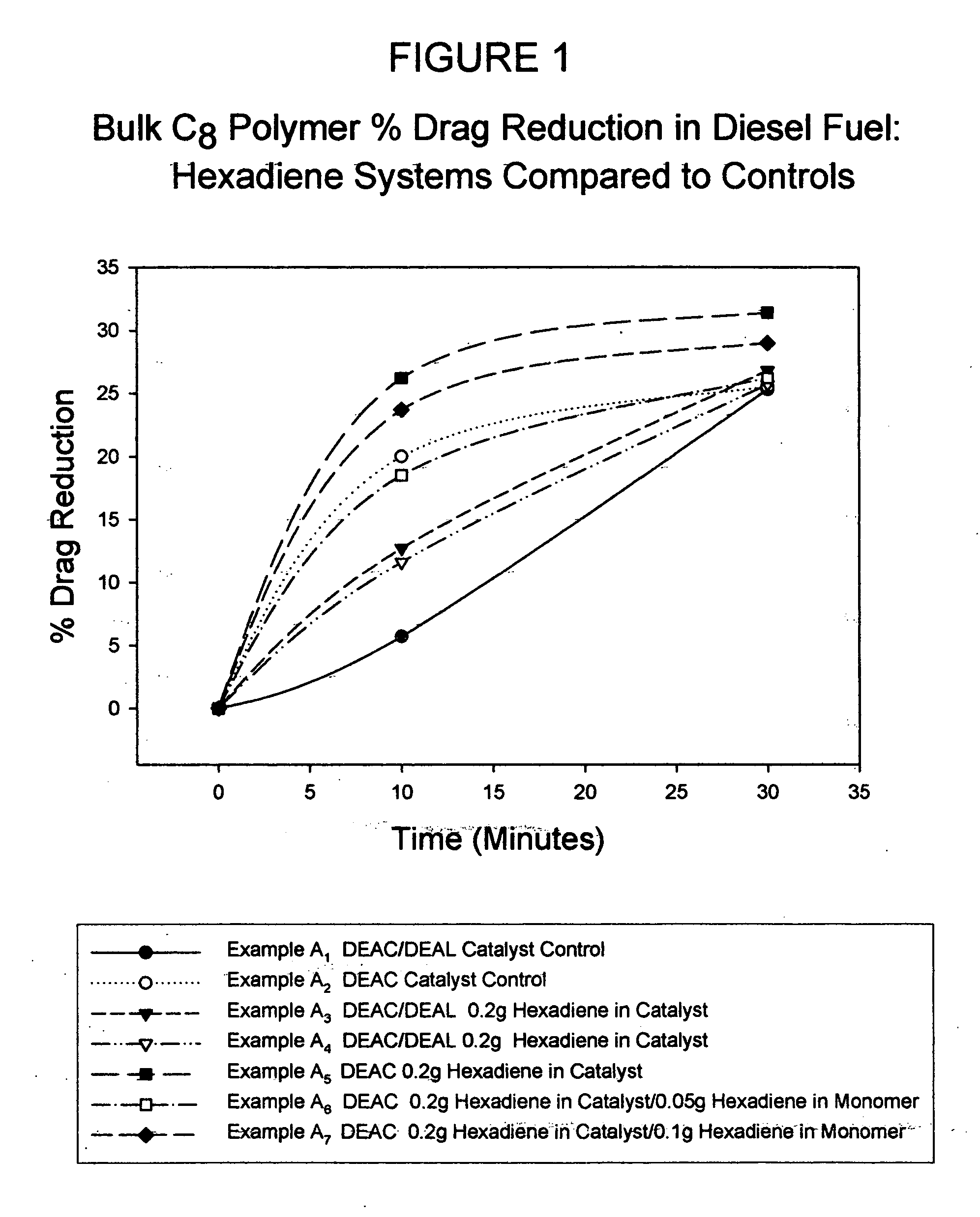
[0037] Preliminary polymerization experiments were conducted in sealable culture tubes submerged in a cold bath. Thus, in each case known quantities of monomer and or di-functional monomer were deposited in a culture tube, the tube sealed and subsequently purged with nitrogen. Upon cooling the tubes and monomer to 25° F. (−3.9° C.), both aluminum alkyl and titanium trichloride (dispersed in mineral oil) were injected into each tube via syringe. Stirring was accomplished by Teflon® coated magnetic stirring bars in the bottom of the tubes. Once the catalyst-activated monomer reached sufficient viscosity such that the stir bar was prohibited from stirring, the tubes were transferred to a refrigerator freezer where polymerization continued for 24 hours. Upon recovery the bulk polymers were granulated and ground to fine particle sizes utilizing a laboratory colloid mill. Dissolution studies were conducted on each polymer and that data can be found in Table I.

[0038] Shown in FIG. 1 is a ...

example 2

[0042] A manufacturing batch of solution polymerized FLO® XLec was produced as an experimental batch in a 6000 gallon reactor. Instead of utilizing the nominal 14% monomer concentration in the reaction, the reactor was charged with 21% monomer. The resulting FLO® XLec was of higher quality or higher drag reduction value vs. the commercial FLO® XLec and was expected to outperform the typical commercial FLO® XLec. However, subsequent field tests revealed poorer performing dissolution characteristics as compared to traditional solution FLO® XLec. It is believed that when monomer concentrations are increased to larger values (18-24%), the beta-hydride elimination or branching mechanism decreases. Thus, polymer molecular weight and linearity increases and solubility decreases.

example 3

[0043] A reactor combination consisting of a 2 gallon (7.6 liter) continuously stirred tank reactor (CSTR) and a 2″ (5 cm) diameter “Shell and Tube” (S&T) static reactor was used to prepare a number of neat or bulk polymers under standard conditions. Thus, a monomer mixture composed of hexene and dodecene at a known ratio weight ratio (400 grams) was charged into the CSTR and allowed to cool to 25° C. Upon reaching 25° C., a previously prepared catalyst mixture consisting of 0.04 gram 1,5-hexadiene, 0.15 gram of titanium trichloride, 2 grams of aluminum alkyl and 20 grams of mineral oil (Drakeol 34 available from Penreco), was charged to the stirring reactor. This catalyzed mixture was allowed to stir for 5 minutes prior to charging via nitrogen pressure to the static S&T reactor. The mixture was subsequently allowed to polymerize for 24 hours in the S&T reactor at a constantly cooled temperature of 30° C. Upon reaction completion, the solid polymer was collected, granulated via War...


PUM

PropertyMeasurementUnit
temperatureaaaaaaaaaa

Abstract

The dissolution of polymeric drag reducing agents (DRAs) in flowing hydrocarbon fluids is improved by incorporating branching into the polymer DRAs. A branched polymer of the same molecular weight will have a smaller overall size because of its reduced radius of gyration (Rg), and thus dissolve more readily. In one non-limiting embodiment, the polymer is a poly(alpha-olefin) and the branches are long-chain branches (Y-branching) and/or induced or H-branching, whereby the induced branch length may have an average chain length of at least 4-8 carbon atoms.

Description

CROSS-REFERENCE TO RELATED APPLICATION [0001] This application claims the benefit of U.S. Provisional Application No. 60 / 689,839 filed Jun. 13, 2005.TECHNICAL FIELD [0002] The invention relates to processes for producing and using polymeric drag reducing agents, and most particularly to processes for providing and using polymeric drag reducing agents that have improved dissolution in the hydrocarbons into which they are introduced. TECHNICAL BACKGROUND [0003] The use of polyalpha-olefins or copolymers thereof to reduce the drag of a hydrocarbon flowing through a conduit, and hence the energy requirements for such fluid hydrocarbon transportation, is well known. These drag reducing agents or DRAs have taken various forms in the past, including slurries or dispersions of ground polymers to form free-flowing and pumpable mixtures in liquid media. A problem generally experienced with simply grinding the polyalpha-olefins (PAOs) is that the particles will “cold flow” or stick together in...

Claims


Application Information

Patent Timeline
Patent Type & Authority Applications(United States)
IPC IPC(8): C09K3/00
CPCC08F210/08C08F210/14F17D1/17C08F2/02C08F2/005C08F236/20
Inventor HARRIS, JEFFERY R.
Owner BAKER HUGHES INC
Why Eureka
Try Eureka