Detection of nuclear materials

Inactive Publication Date: 2006-12-21
INBAR DAN
View PDF99 Cites 151 Cited by
  • Summary
  • Abstract
  • Description
  • Claims
  • Application Information

AI Technical Summary

Benefits of technology

[0100] Generally, the Nuclear-Radiological Threat Screening Portals according to some embodiments of the present invention substantially depart from the conv

Problems solved by technology

The prior art thinking is that since plastic scintillators do not provide energy resolution and thus cannot provide spectroscopy isotope ID, such detectors result in a high rate of false and nuisance alarms.
In spite of their inherent limitations (see Table 4), plastic scintillators are used extensively in present-day nuclear/radiological portals, mainly due to the low cost of large volume (5-50 liter) plastic scintillators as detectors without effective energy resolution.
In a scintillator crystal, the return of the atom to lower-energy states with the emission of photons is an inefficient process.
Ne

Method used


Image

  • Detection of nuclear materials
  • Detection of nuclear materials
  • Detection of nuclear materials

Examples


Example

Exemplary Architecture

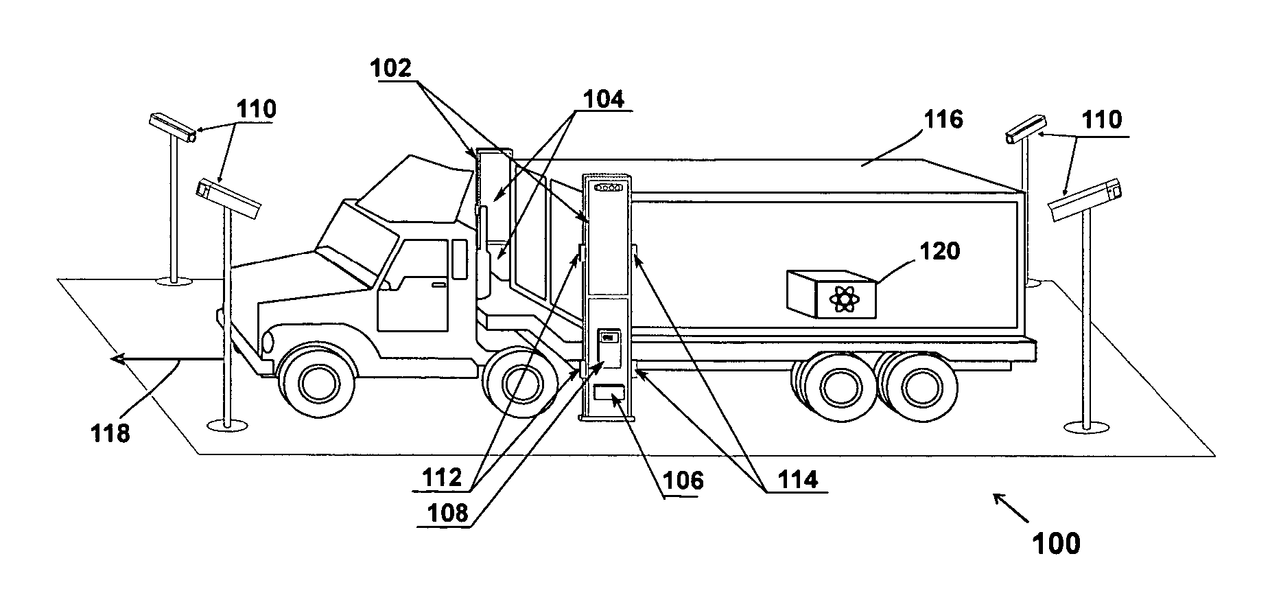
[0176] An exemplary architecture of a detection system portal 100 according to some aspects of the invention is shown in FIG. 12. This embodiment includes two support stands 102, one on each side of the portal's lane, at least one and preferably both having at least one radiation detection panel 104. Each such panel includes a detector bank and an “electronics package” (described below). Each support stand is shown as having two panels in this embodiment. This allows for using a smaller and more manageable panel to provide a sufficient height to scan large vehicles.

[0177] Optionally, the portal includes an uninterrupted power source 106. Control signals and the radiation sensor panels' data are cable-linked (or wireless linked) between a control box 108 and the “detection assemblies”, and the optional ancillary units (e.g., object ID (e.g., vehicle, train, people, packages) sensors vehicle ID systems 110, break beam sensors 112 and vehicle speed sensors 114)...


PUM


Abstract

A method for detecting Special Nuclear Materials (SNM) or Radiological dispersion Devices (RDD), comprising: conveying an object along a predetermined path; imaging a distribution of radioactive sources associated with the object as it passes along said path; determining the presence and location of one or both of an RDD or SNM radioactive source within the object.

Description

RELATED APPLICATIONS [0001] This application claims the benefit under 35 U.S.C. §1.19(e) of U.S. provisional applications 60 / 649,541 “Nuclear Radiological Threats Screening Portals,” filed: Feb. 4, 2005; 60 / 651,622 “SNM and RDD Screening Portals,” filed: Feb. 11, 2005; and 60 / 654,964 “Advanced SNM and RDD Screening Portals”, filed Feb. 23, 2005. The disclosures of each of these applications is incorporated herein by reference.FIELD OF THE INVENTION [0002] The present application is generally concerned with detection of nuclear materials. BACKGROUND OF THE INVENTION [0003] Nuclear-Radiological (hereunder occasionally referred to as “nuc / rad” or SNM / RDD) Threat Screening Portals have been developed starting with the Manhattan project (1942-1946). These systems were developed mainly to ensure workplace and product safety in the nuclear industry with its estimated 1,000 nuclear facilities worldwide and in the scrap metal industry. [0004] Since the early 1990s, industry and national labs...

Claims


Application Information

Patent Timeline
IPC IPC(8): G01T3/00
CPCG01V5/0091G01V5/0075
Inventor INBAR, DAN
Owner INBAR DAN
Why Eureka
Try Eureka