Power converter and semiconductor device mounting structure
- Summary
- Abstract
- Description
- Claims
- Application Information
AI Technical Summary
Benefits of technology
Problems solved by technology
Method used
Image


Examples
first embodiment
[0072] An electric power converter in accordance with a first embodiment of the present invention will next be explained by using FIGS. 1 to 4. An electric power converter 1 according to the first embodiment is an electric power converter for a hybrid automotive vehicle. As shown in FIG. 1, the electric power converter 1 is constructed by a main circuit section 10, a control circuit substrate section 2 and a power wiring section 3. The main circuit section 10 is interposed between the control circuit substrate section 2 and the power wiring section 3.
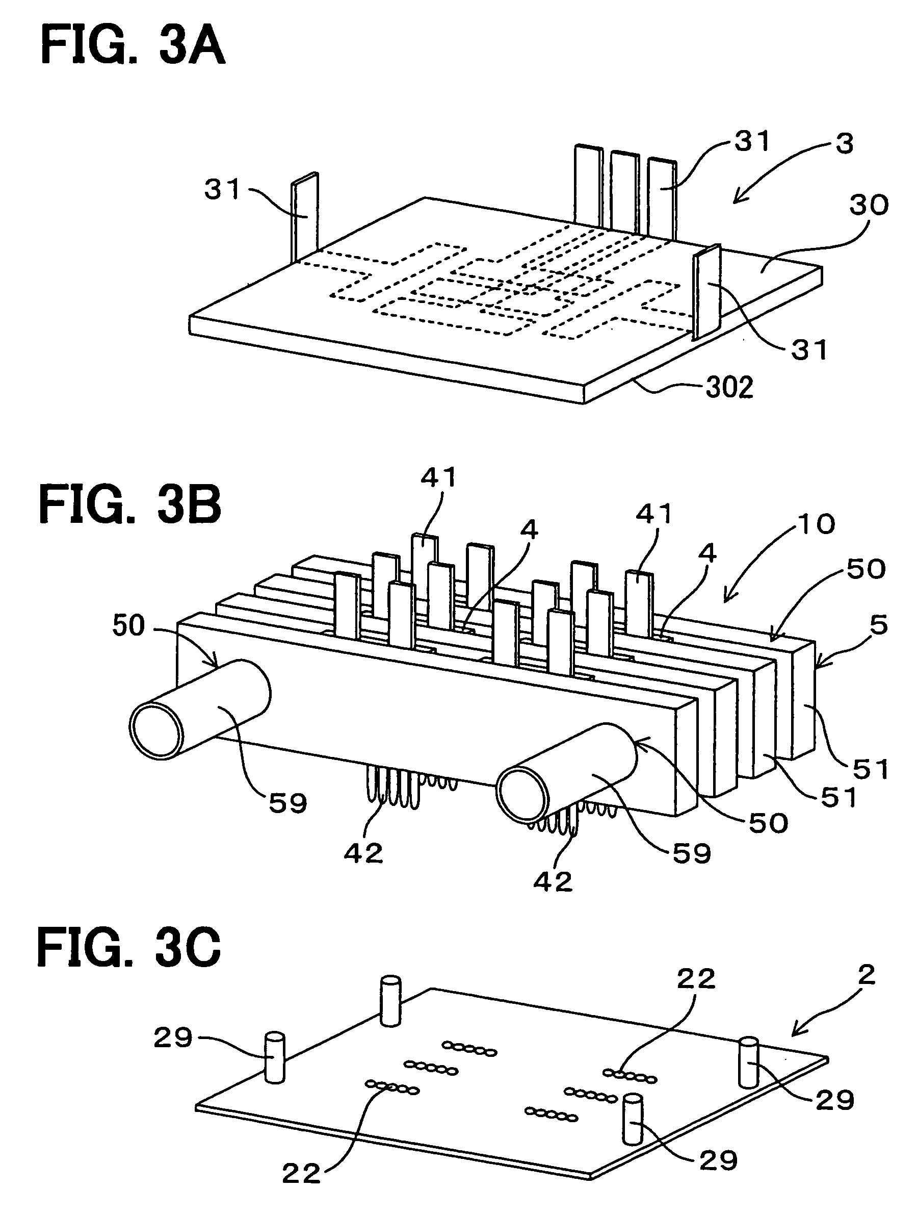
[0073] As shown in FIGS. 2 and 3A, 3B, 3C, the main circuit section 10 is constructed by including a semiconductor module 4 constituting one portion of the electric power converting circuit, and a cooling device 5 for cooling this semiconductor module 4. The control circuit substrate section 2 is a substrate electrically connected to a signal terminal 42 of the semiconductor module 4, and having an unillustrated control circuit for con...
second embodiment
[0084] As shown in FIG. 5, a second embodiment is an example in which a reactor 61 and a capacitor 62 constituting one portion of a voltage raising circuit are arranged in the power wiring section 3 of the electric power converter 1 on the basis of the electric power converter 1 according to the first embodiment. In this case, it is possible to restrain the influence of electric noises from the reactor 61 and the capacitor 62 as electronic parts constituting the voltage raising circuit to the control circuit substrate section 3. With respect to the others, operations and effects similar to those in the first embodiment are obtained.
[0085] 2. Mounting Structure
[0086] Next, the second embodiment of the mounting structure of a semiconductor device in the present invention will be explained. This mounting structure of the semiconductor device can be classified into the following three types in accordance with a forming method of a bypass capacitor for noise restraint, particularly, wh...
third embodiment
[0094] A driving system of a hybrid automotive vehicle shown in FIG. 7 includes a battery 1010, an motor generator (MG) 1020 and an inverter device 1060. A smoothing capacitor 1013 and a semiconductor pair for a three-phase alternating current (U-phase, V-phase and W-phase) constituting the inverter device 1060 are arranged between direct current bus bars 1011 and 1012 extended from a positive electrode terminal and a negative electrode terminal of the battery 1010. A U-phase line 1016 is extended to MG 1020 from between first and second U-phase semiconductor elements 1031 and 1032.
[0095] A V-phase line 1017 is extended to MG 1020 from between first and second V-phase semiconductor elements 1031 and 1032. A W-phase line 1018 is extended to MG 1020 from between first and second W-phase semiconductor elements 1031 and 1032.
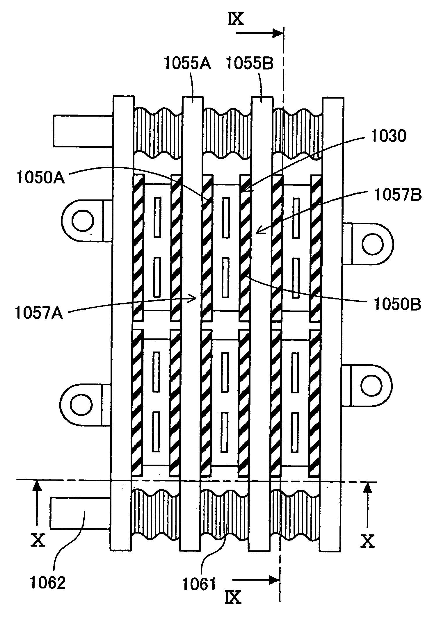
[0096] As shown in FIGS. 8 to 10, the inverter device 1060 is constructed by alternately laminating a holding pipe 1055 and plural semiconductor modules 1030 thro...
PUM
 Abstract
Description
Claims
Application Information
 - Generate Ideas
- Intellectual Property
- Life Sciences
- Materials
- Tech Scout
- Unparalleled Data Quality
- Higher Quality Content
- 60% Fewer Hallucinations
Browse by: Latest US Patents, China's latest patents, Technical Efficacy Thesaurus, Application Domain, Technology Topic, Popular Technical Reports.
© 2025 PatSnap. All rights reserved.Legal|Privacy policy|Modern Slavery Act Transparency Statement|Sitemap|About US| Contact US: help@patsnap.com