
Heterogeneous electrochemical supercapacitor and method of manufacture

Inactive Publication Date: 2006-12-28
UNIVERSAL SUPERCAPACITORS LLC
View PDF62 Cites 24 Cited by
  • Summary
  • Abstract
  • Description
  • Claims
  • Application Information

AI Technical Summary

Benefits of technology

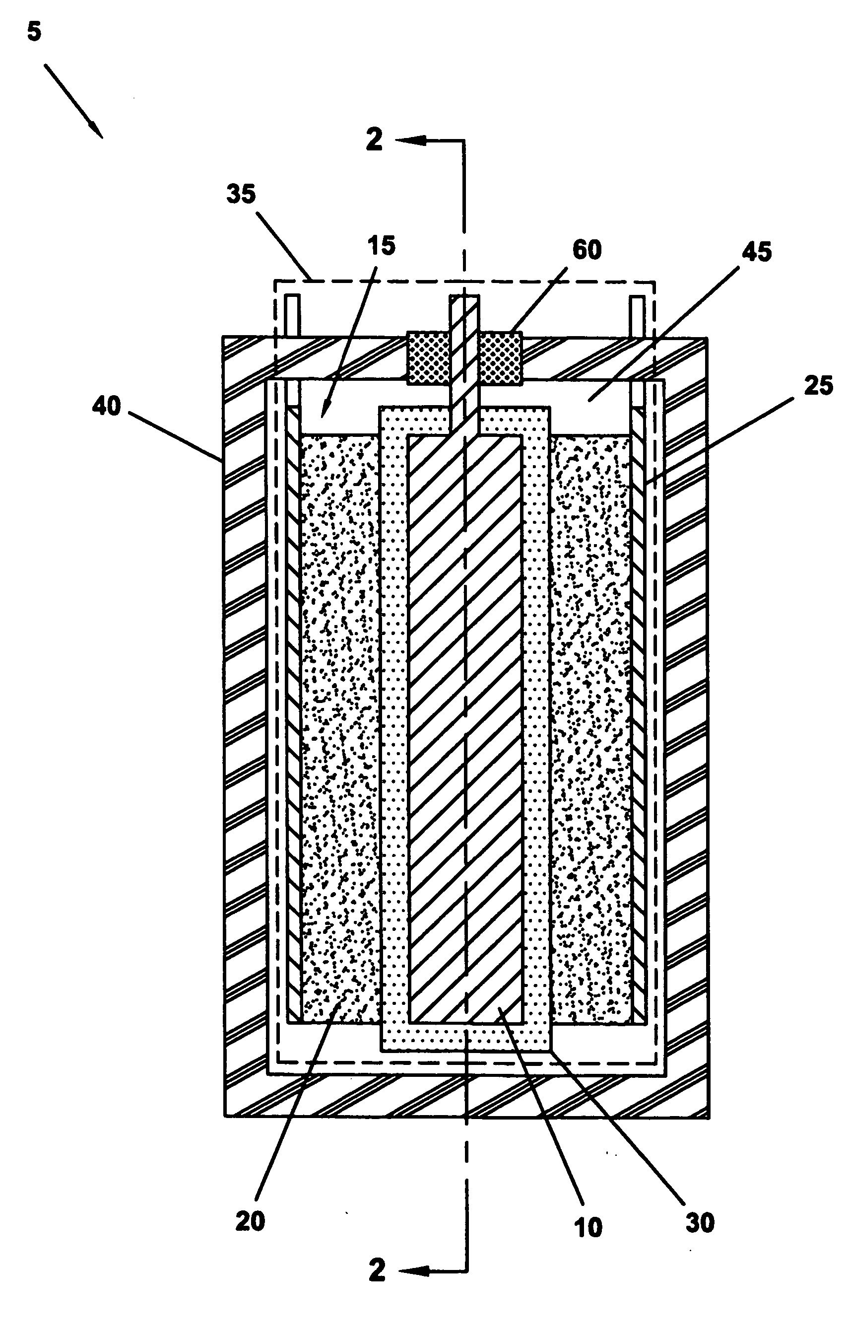
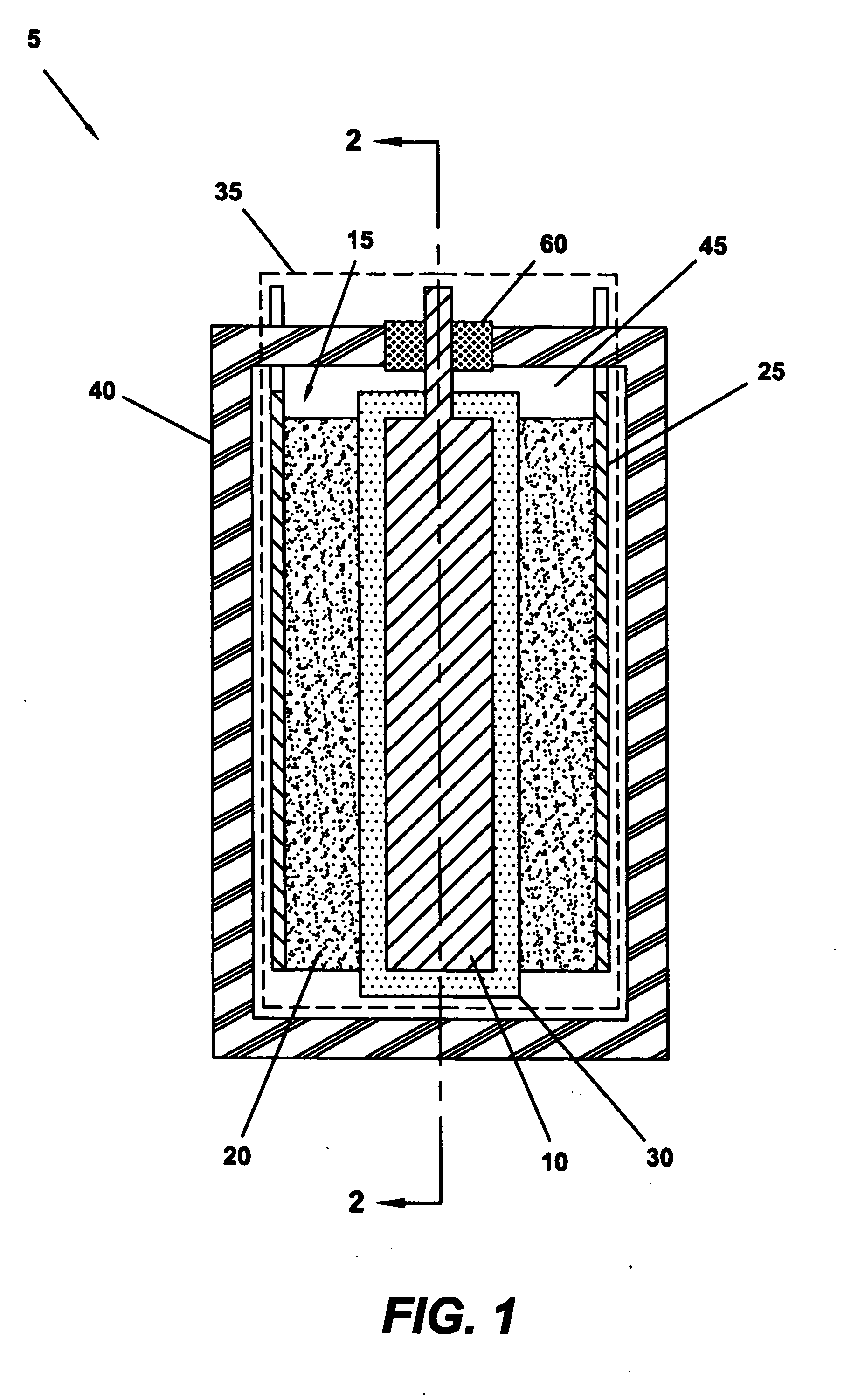
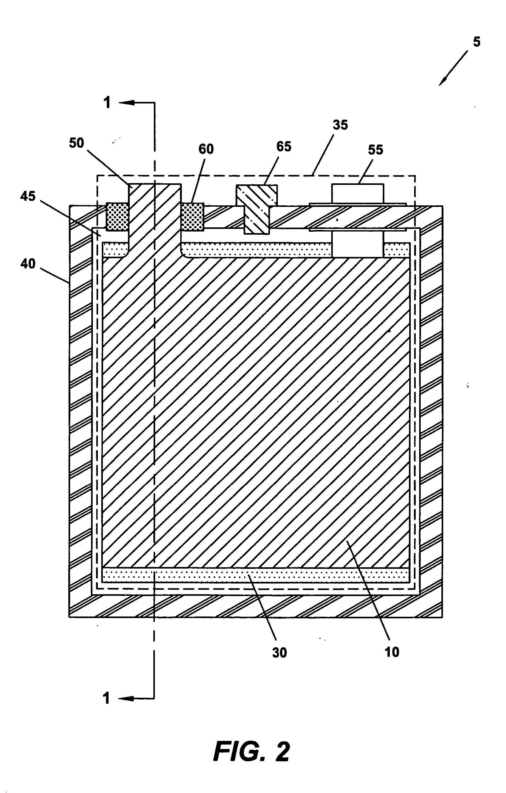
[0009] The HES of the present invention offers advantages over known electrochemical capacitor designs, including that of other HES'. For example, the design and manufacture of a HES according to the present invention provides for an electrochemical capacitor of high discharge power. A HES of the present invention also exhibits high specific power characteristics, whether measured by weight or by volume. In addition, the method of manufacturing the HES allows for lower production costs and reduced assembly time. A HES of the present invention also has high cycling capacity (a long life cycle).
[0010] The aforesaid advantages afforded by a HES of the present invention are the result of at least several factors. First, the ratio between the charging capacities of the positive electrode and negative electrode of the HES is carefully selected and controlled. An active material of higher efficiency than the active material used by typical electrochemical capacitors is also utilized in the construction of both the positive and negative electrodes of the HES of the present invention. A HES of the present invention further employs a separator with improved operating parameters. Additionally, the negative electrode current collector is preferably manufactured from a material having a matching layer, which ensures high conductivity, high hydrogen gassing overpotential and high stability within a range of negative electrode operating voltages within the electrolyte environment of the HES.

Problems solved by technology

However, there are disadvantages to many of these known electrochemical capacitor designs.
For example, one concern with the use of electrochemical capacitors is cost—both the cost to manufacture the capacitors, and the cost of storing energy therewith.
These materials are considerably more expensive than the lead material typically used in a HES.
Consequently, both the cost to manufacture and the cost to store energy using electrochemical capacitors of typical design can often be prohibitive.

Method used


Image

  • Heterogeneous electrochemical supercapacitor and method of manufacture
  • Heterogeneous electrochemical supercapacitor and method of manufacture
  • Heterogeneous electrochemical supercapacitor and method of manufacture

Examples


example 1

[0041] A multi-cell HES having 7 positive and 8 negative electrodes was assembled in a case. The positive and negative electrodes were separated by a porous separator. The positive electrodes were formed from a mixture of Pb, Pb3O4, and PbO powders that was made into a paste and introduced to a grid of lead and antimony (5%) alloy. The active mass of the negative electrodes was manufactured from an activated carbon material, as described above, and attached to a current collector comprised of lead and tin (3%) alloy. Both the positive and negative electrodes were formed in the shape of flat plates for insertion into a case. The cells were filled with an aqueous sulfuric acid electrolyte, and the case was sealed.

example 2

[0042] A multi-cell HES having 7 positive and 8 negative electrodes was assembled in a case. The positive and negative electrodes were separated by a porous separator. The positive electrodes were formed from a mixture of Pb, Pb3O4, and PbO powders that was doped with admixtures of Ti7O13 and Ti8O15 in a weight ratio of 85%:15%, respectively. The mixture was made into a paste, and was introduced to a grid of lead and antimony (5%) alloy. The active mass of the negative electrodes was manufactured from an activated carbon material, as described above, and attached to a current collector comprised of lead and tin (3%) alloy. Both the positive and negative electrodes were formed in the shape of flat plates for insertion into a case. Once cell assembly was complete, the cells were filled with an aqueous sulfuric acid electrolyte. After a soaking period, the positive electrodes were subjected to the forming process.

example 3

[0043] A multi-cell HES having 7 positive and 8 negative electrodes was assembled in a case. The positive and negative electrodes were separated by a porous separator. In one variation, the positive electrodes were formed from a mixture of Pb, Pb3O4, and PbO powders that was doped with a bismuth (Bi2O3) powder during paste preparation. In another variation, the positive electrodes were formed by soaking PbO with an acetone solution of bismuth nitrate (Bi(NO3)3 .5H20). A Pb3O4 powder was then obtained from the mixture and used to form a paste. In both variations, the paste was introduced to a grid of lead and antimony (5%) alloy. The active mass of the negative electrodes was manufactured from an activated carbon material, as described above, and attached to a current collector comprised of lead and tin (3%) alloy. Both the positive and negative electrodes were formed in the shape of flat plates for insertion into a case. Once cell assembly was complete, the cells were filled with an...


PUM


Abstract

The present invention relates to a double electric layer heterogeneous electrochemical supercapacitor (HES) and a method of manufacture. Single-cell or multi-cell versions of the HES can be produced. Output characteristics of the HES are optimized by carefully controlling particular parameters of the HES' design and construction. For example, the ratio between the charging capacities of the positive electrode and negative electrode of the HES is carefully selected and controlled, an active material of higher efficiency than the active material used by typical electrochemical capacitors is preferably utilized in the construction of both the positive and negative electrodes, a separator with improved operating parameters is used, and the negative electrode current collector is preferably manufactured from a material having a matching layer—which ensures high conductivity, high hydrogen gassing overpotential, and high stability within a range of negative electrode operating potentials within the electrolyte environment of the HES.

Description

[0001] This application claims the benefit of PCT Application Ser. No. PCT / RU2005 / 000344, filed on Jun. 24, 2005.BACKGROUND OF THE INVENTION [0002] The present invention relates to a heterogeneous electrochemical supercapacitor (HES), and to a method for manufacturing such a capacitor. More particularly, the present invention is directed to an improved HES. A HES of the present invention exhibits superior operating parameters in comparison to other electrochemical capacitors of known design. [0003] There is an increasing focus on the use of double electric layer (DEL) electrochemical capacitors as a means for storing electrical energy. Among known electrochemical capacitors the HES typically exhibits the highest specific energy while simultaneously providing for electrical energy storage at the lowest cost. In the electrodes of conventional electrochemical capacitors, electric charge exists in a free state and the energy of both electrodes is potential energy. Unlike conventional ca...

Claims


Application Information

Patent Timeline
IPC IPC(8): H01G9/00H01G11/30H01G11/46
CPCH01G11/46H01G11/58H01G11/30Y02E60/13
Inventor KAZARYAN, SAMVEL AVAKOVICHKHARISOV, GAMIR GALIEVICHKAZAROV, VLADIMIR ALEXANDROVICHLITVINENKO, SERGEY VITALIEVICHRAZUMOV, SERGEY NIKOLAEVICH
Owner UNIVERSAL SUPERCAPACITORS LLC
Learn More