Digital motor control system and method

a digital motor and control system technology, applied in the direction of dynamo-electric converter control, ac motor direction control, dc motor rotation control, etc., can solve the problems of inefficiency, high cost and low efficiency of the system, and the inability of the prior art servo control system to provide the rotation direction control of the motor, etc., to achieve stable, energy-efficient, and servo control

Active Publication Date: 2006-12-28
KOBAYASHI HERBERT S
View PDF23 Cites 33 Cited by
  • Summary
  • Abstract
  • Description
  • Claims
  • Application Information

AI Technical Summary

Benefits of technology

[0019] It is another object of the present invention to provide a stable, energy efficient, servo control system.

Problems solved by technology

Prior art servo control systems often either do not provide motor rotation direction control or have problems related to changing the motor rotation direction.
However, depending on operation demands, the power transistor may dissipate a lot of power thereby making the system more expensive and less efficient.
Inefficiencies in this system are especially large around the null error signal level, i.e., where the motor is at the null between forward and reverse directions.
However, stabilization is difficult because there is no continuous error signal provided at the null position.
Therefore, the pulse width variation type of control is not readily adaptable to stable operation of closed loop servo systems.

Method used


Image

  • Digital motor control system and method
  • Digital motor control system and method
  • Digital motor control system and method

Examples


Embodiment Construction

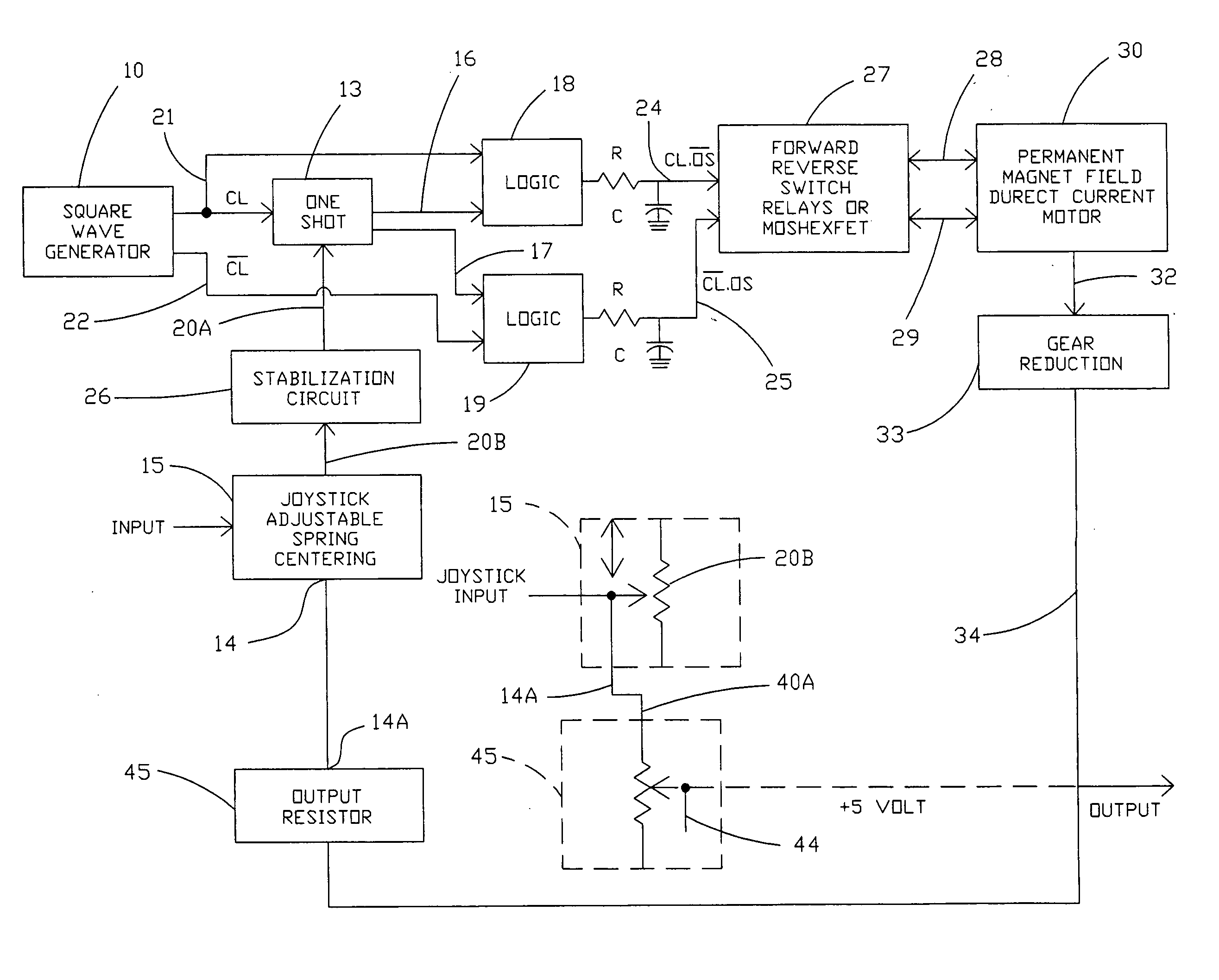
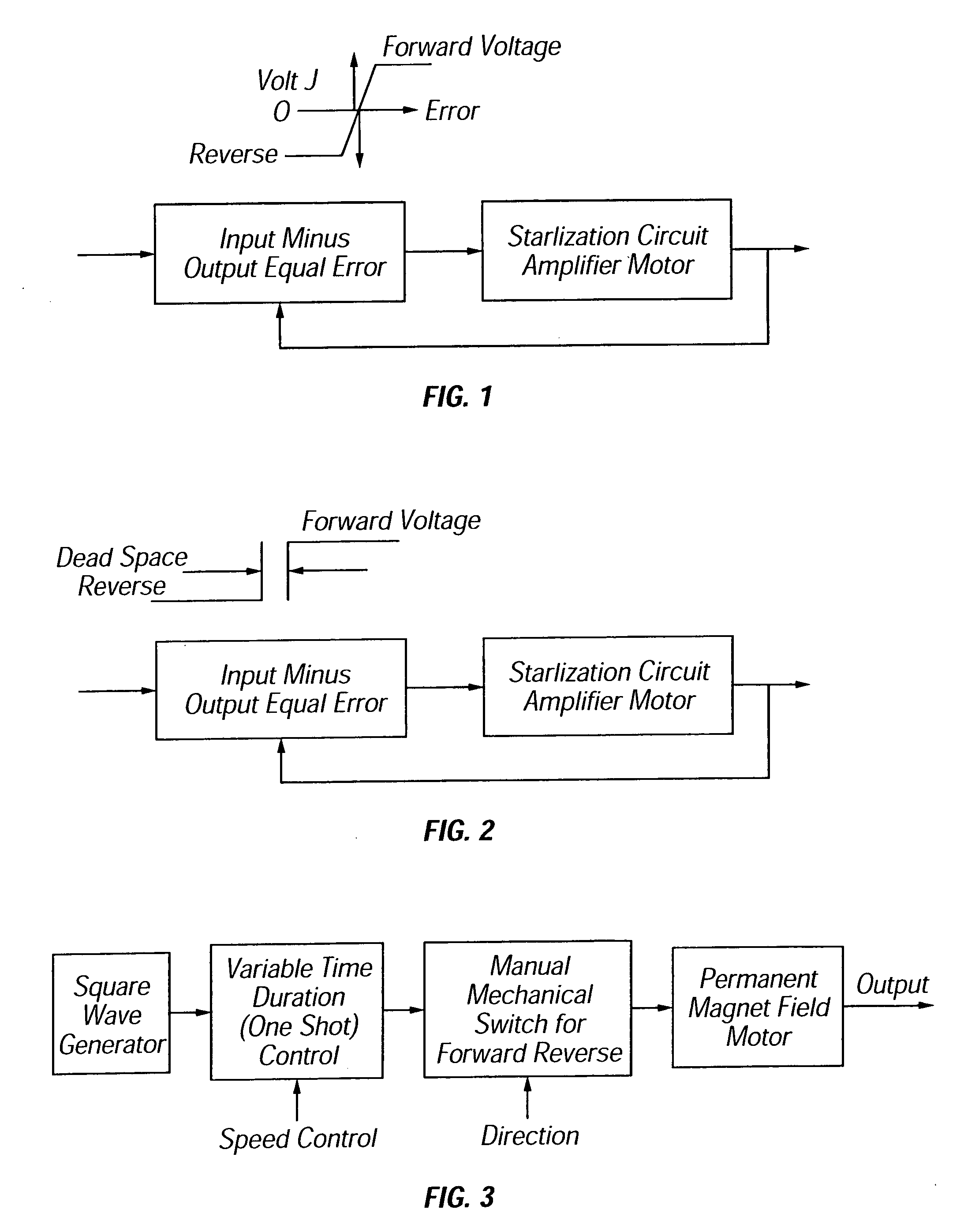
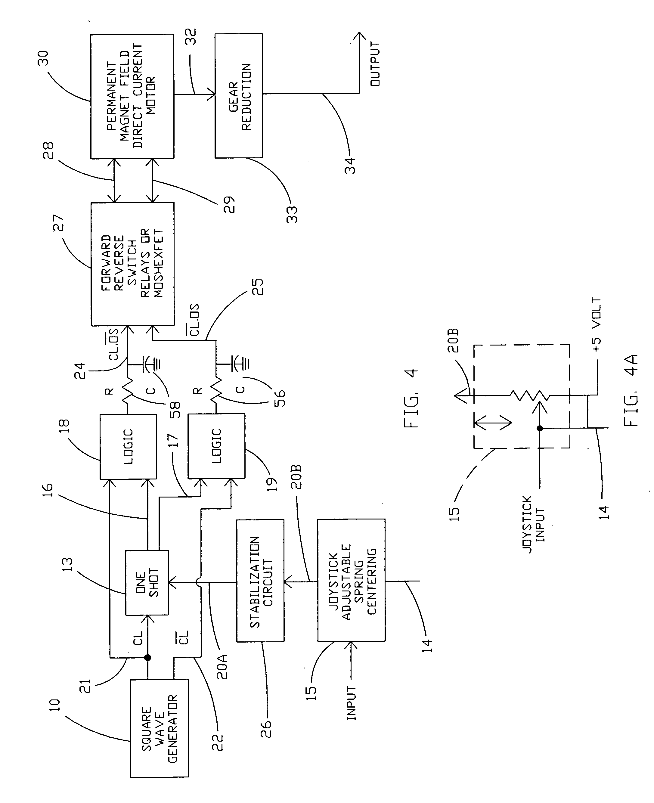
[0042] The present invention provides linear motor control using pulse width modulation. In one embodiment, the error signal is a produced as a result of pulse width modulation signals applied to the motor. The present invention may utilize MOSFET and / or other solid state relay devices which provide a very low resistance during operation or in the on state. This results in low power loss, low cost, low weight, and increased efficiency of the motor speed control system.

[0043] Referring now to the drawings and more particularly to FIG. 4, there is shown a block diagram of one possible embodiment of the invention with an open loop servo time duration control system and digital logic for control of the motor speed and direction of motor rotation using an analog sensor such as a variable resistance. While relatively simple logic circuits may be utilized for implementing the invention, it will be understood that the invention may also be implemented utilizing a suitably programmed microp...


PUM


Abstract

A digital motor control system utilizes time duration electric pulses generated by digital logic to control the motor speed and direction of rotation of a D.C. or A.C. motor. The digital logic produces width modulated pulses that can be connected to large or small electric motors by mechanical or electrical relays or switches to provide efficient motor control with little control circuit power loss. The mechanical or electrical switches are responsive to the digital logic to change motor direction or remove power from the motor windings. A variable control element such as a computer joystick can be utilized to control both direction and speed of the motor. The system can be configured as an open loop system or as a closed loop servo with a feed back element to control the rotational position of the motor.

Description

BACKGROUND OF THE INVENTION [0001] 1. Field of the Invention [0002] The present invention relates generally to motor control systems and, more particularly, to a pulse width modulation digital motor control system to control both the motor speed and direction of rotation for D.C. or A.C. electric motors. [0003] 2. Description of the Background [0004] Prior art servo control systems often either do not provide motor rotation direction control or have problems related to changing the motor rotation direction. The speed of a servo motor and its direction of rotation are conventionally controlled in a linear or analog servo loop as shown in FIG. 1 by controlling the amplitude and polarity of a signal applied to a power transistor included in the loop. However, depending on operation demands, the power transistor may dissipate a lot of power thereby making the system more expensive and less efficient. Inefficiencies in this system are especially large around the null error signal level, ...

Claims


Application Information

Patent Timeline
Patent Type & Authority Applications(United States)
IPC IPC(8): H02P7/06
CPCH02P23/0072H02P7/0038H02P23/24H02P7/03
Inventor KOBAYASHI, HERBERT S.
Owner KOBAYASHI HERBERT S
Why Eureka
Try Eureka