Honeycomb structure

Active Publication Date: 2006-12-28
IBIDEN CO LTD
View PDF45 Cites 58 Cited by
  • Summary
  • Abstract
  • Description
  • Claims
  • Application Information

AI Technical Summary

Benefits of technology

[0043] According to the honeycomb structure of the present invention, it is possible to highly disperse the catalyst elements and improve resistance against thermal shock and vibration.

Problems solved by technology

However, if simply increasing the amount of the materials of high specific surface areas like active alumina, it is the thickness of the active alumina layer only that is increased, and it does not lead to an increase of the contact probability, but results in a pressure loss.

Method used


Image

  • Honeycomb structure
  • Honeycomb structure
  • Honeycomb structure

Examples


example 1

[0095] First, γ alumina particles (having average particle diameter of 2 μm) in 40 parts by weight, serving as the ceramic particles, silica alumina fibers (having average fiber diameter of 10 μm, average fiber length of 100 μm, aspect ratio of 10) in 10 parts by weight, serving as the inorganic fibers, and silica sol (solid concentration 30 weight %) in 50 parts by weight, serving as the raw materials of the inorganic binder, are mixed. Further, methylcellulose in 6 parts by weight and tiny amounts of plasticizer and lubricant are added into the thus obtained mixture in 100 parts by weight, and are further mixed and kneaded, forming a mixture composition. Then, this mixture composition is extruded by using an extruder to perform extrusion molding, obtaining a raw molding piece.

[0096] A microwave dryer and a hot air dryer are used to adequately dry the raw molding piece, and then the raw molding piece is maintained at 400° C. for two hours for degreasing. Afterward, the raw molding...

examples 2 , 3

EXAMPLES 2, 3, COMPARATIVE EXAMPLES 1-3, AND REFERENCE EXAMPLE 1

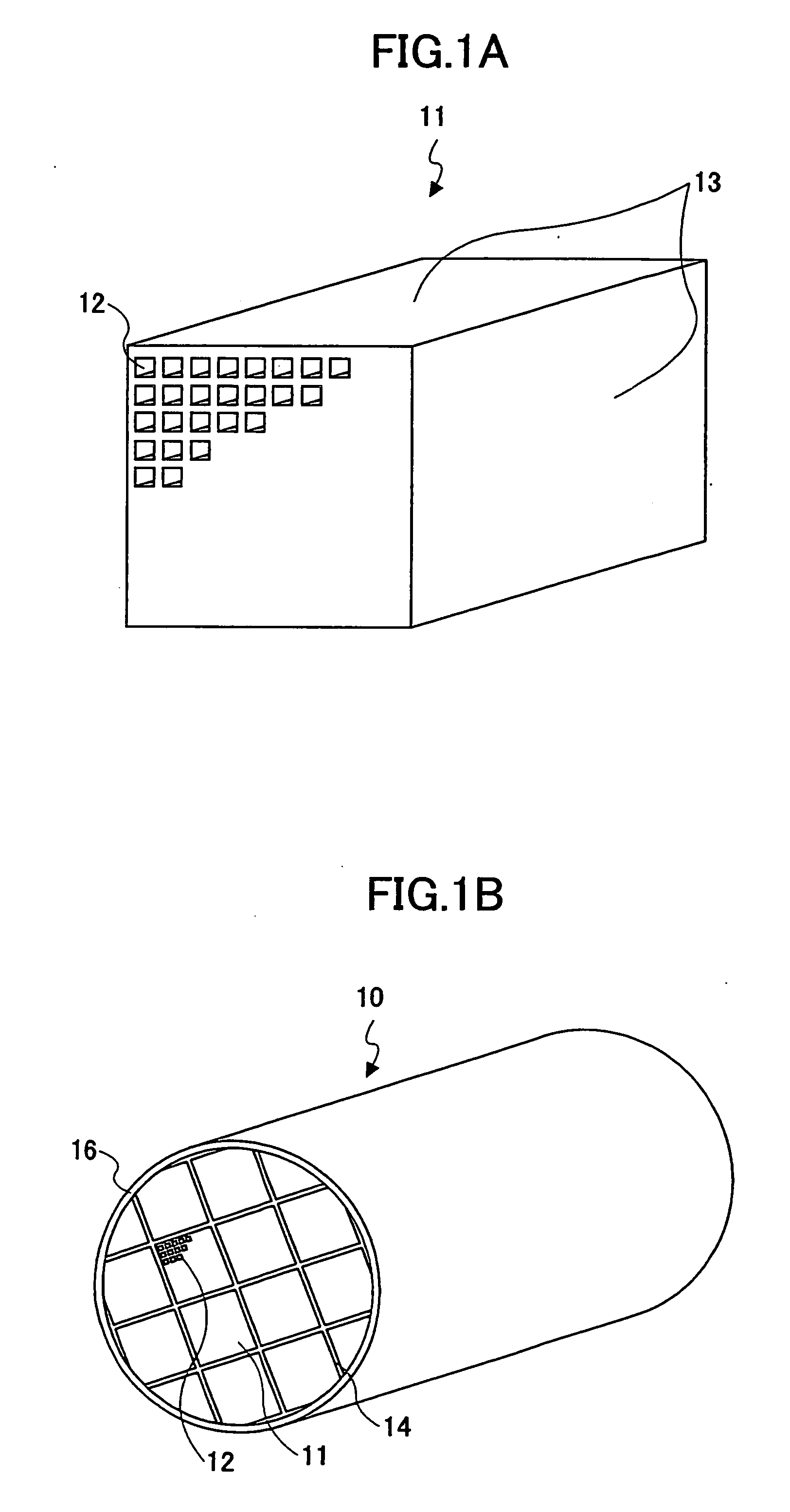
[0105] Honeycomb structures 10 were fabricated in the same way as in the first example with the shapes of the honeycomb units to be those displayed in Table 1. Specifically, FIG. 4B, FIG. 4C, and FIG. 4D show honeycomb structures 10 of comparative example 1, example 2, and reference example 1, and FIG. 5A, FIG. 5B, and FIG. 5C show honeycomb structures 10 of example 3 and comparative examples 2, 3.

[0106] In the comparative example 3, the honeycomb structures 10 is formed integrally, hence, the bonding step and the cutting step were not performed.

example 4

[0108] A honeycomb structure 10 was fabricated as below. A heat-resistant sealing paste was prepared by mixing SiC particles (having average particle diameter of 0.5 μm) in 29 parts by weight, silica alumina fibers (having average fiber diameter of 10 μm, and average fiber length of 100 μm) in 7 parts by weight, silica sol (solid concentration 30 weight %) in 34 parts by weight, carboxymethylcellulose in 5 parts by weight, and water in 25 parts by weight. Then, with this sealing paste, plural honeycomb units 11 were bonded to fabricate a honeycomb structure in the same way as in the first example. The shape of the fabricated honeycomb structure 10 is the same as that shown in FIG. 4A.


PUM


Abstract

A honeycomb structure is disclosed that includes plural honeycomb units bonded together by using a sealing material layer, each of the honeycomb units including plural through-holes separated by plural partition walls and provided in parallel along a longitudinal direction. Each of the honeycomb units includes at least ceramic particles, and inorganic fibers and / or whiskers; a cross sectional area of the honeycomb unit is from about 5 cm2 to about 50 cm2; and an outer surface of each honeycomb unit and the sealing material layer satisfy: about 0.5≦κ / d×(dc / κc+df / κf)≦about 1, where, κf (W / mK) and df (mm) represent a thermal conductivity and a thickness of the outer surface of the honeycomb units, respectively, κc (W / mK) and dc (mm) represent a thermal conductivity and a thickness of the sealing material layer, respectively, and κ (W / mK) and d (mm) represent a thermal conductivity and a thickness of the combination of the outer surface and the sealing material layer.

Description

BACKGROUND OF THE INVENTION [0001] 1. Field of the Invention [0002] The present invention relates to a honeycomb structure. [0003] 2. Description of the Related Art [0004] Generally, a honeycomb catalyst, which is used for conversion of exhaust gas from vehicles, is fabricated by disposing materials of a high specific surface area like active alumina and catalysts like platinum on the surface of a monolithic cordierite-based honeycomb structure having a low thermal expansion characteristic. In addition, the honeycomb catalyst carries an alkali-earth metal like barium to act as an occlusion-type NOx catalyst for a NOx processing in an oxygen-rich atmosphere, such as atmospheres in a lean-burn engine or a Diesel engine. [0005] In order to further improve conversion performance, it is necessary to increase the contact probability between the exhaust gas and the catalyst element and the NOx occlusion agent as well. For this purpose, it is required to increase the specific surface area o...

Claims


Application Information

Patent Timeline
IPC IPC(8): B32B3/12
CPCB01D39/2086Y10T428/24157Y10T428/24149B01D39/2089
Inventor OHNO, KAZUSHIGEKUNIEDA, MASAFUMIOGYU, KAZUTAKE
Owner IBIDEN CO LTD
Why Eureka
Try Eureka