AI technical title is built by PatSnap AI team. It summarizes the technical point description of the patent document.
a honeycomb and structure technology, applied in the field of honeycomb structure, can solve the problems of pressure loss, increase of contact probability,
Inactive Publication Date: 2006-12-28
IBIDEN CO LTD
View PDF59 Cites 77 Cited by
Summary
Abstract
Description
Claims
Application Information
AI Technical Summary
This helps you quickly interpret patents by identifying the three key elements:
Problems solved by technology
Method used
Benefits of technology
Benefits of technology
[0041] According to the honeycomb structure of the present invention, it is possible to highly disperse the catalyst elements and improve resistance against thermal shock and vibration.
Problems solved by technology
However, if simply increasing the amount of the materials of high specific surface-to areas like active alumina, it is the thickness of the active alumina layer only that is increased, and it does not lead to an increase of the contact probability, but results in a pressure loss.
Method used
Image
Click on the blue label to locate the original text in one second.
Reading with bidirectional positioning of images and text.
Examples
example 1
[0093] First, γ alumina particles (having average particle diameter of 2 μm) in 40 parts by weight, serving as the ceramic particles, silica alumina fibers (having average fiberdiameter of 10 μm, average fiber length of 100 μm, aspect ratio of 10) in 10 parts by weight, serving as the inorganic fibers, and silica sol (solid concentration 30 weight %) in 50 parts by weight, serving as the raw materials of the inorganic binder, are mixed. Further, methylcellulose in 6 parts by weight and tiny amounts of plasticizer and lubricant are added into the thus obtained mixture in 100 parts by weight, and are further mixed and kneaded, forming a mixture composition. Then, this mixture composition is extruded by using an extruder to perform extrusion molding, obtaining a raw molding piece.
[0094] A microwave dryer and a hot air dryer are used to adequately dry the raw molding piece, and then the raw molding piece is maintained at 400° C. for two hours for degreasing. Afterward, the raw molding...
examples 2 , 3
EXAMPLES 2, 3, COMPARATIVE EXAMPLES 1-3, AND REFERENCE EXAMPLE 1
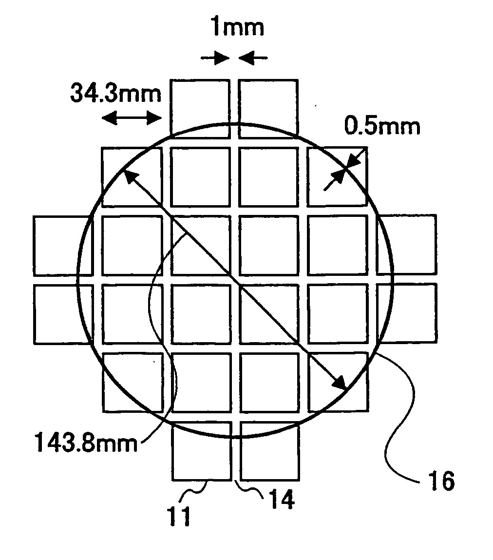
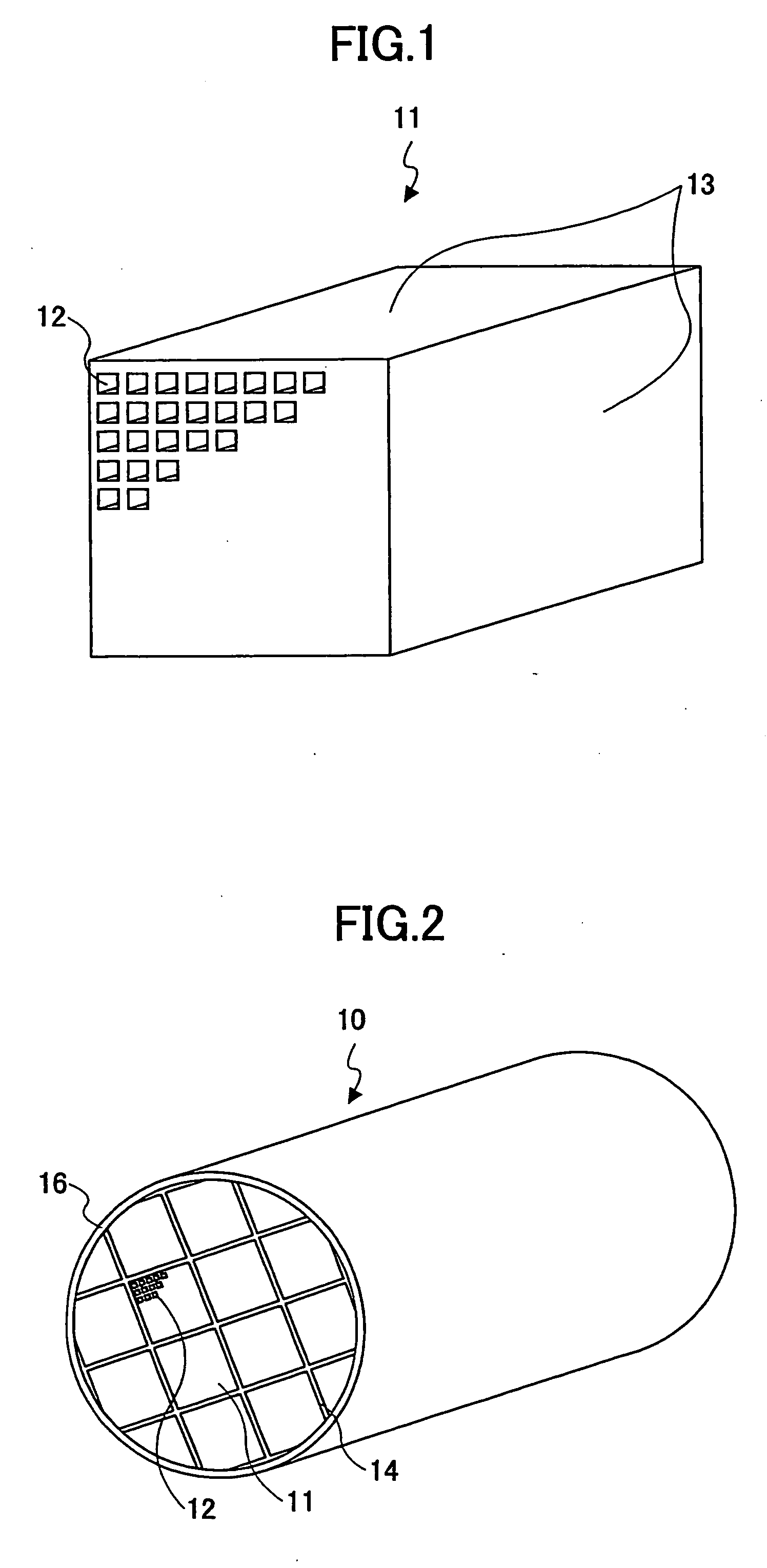
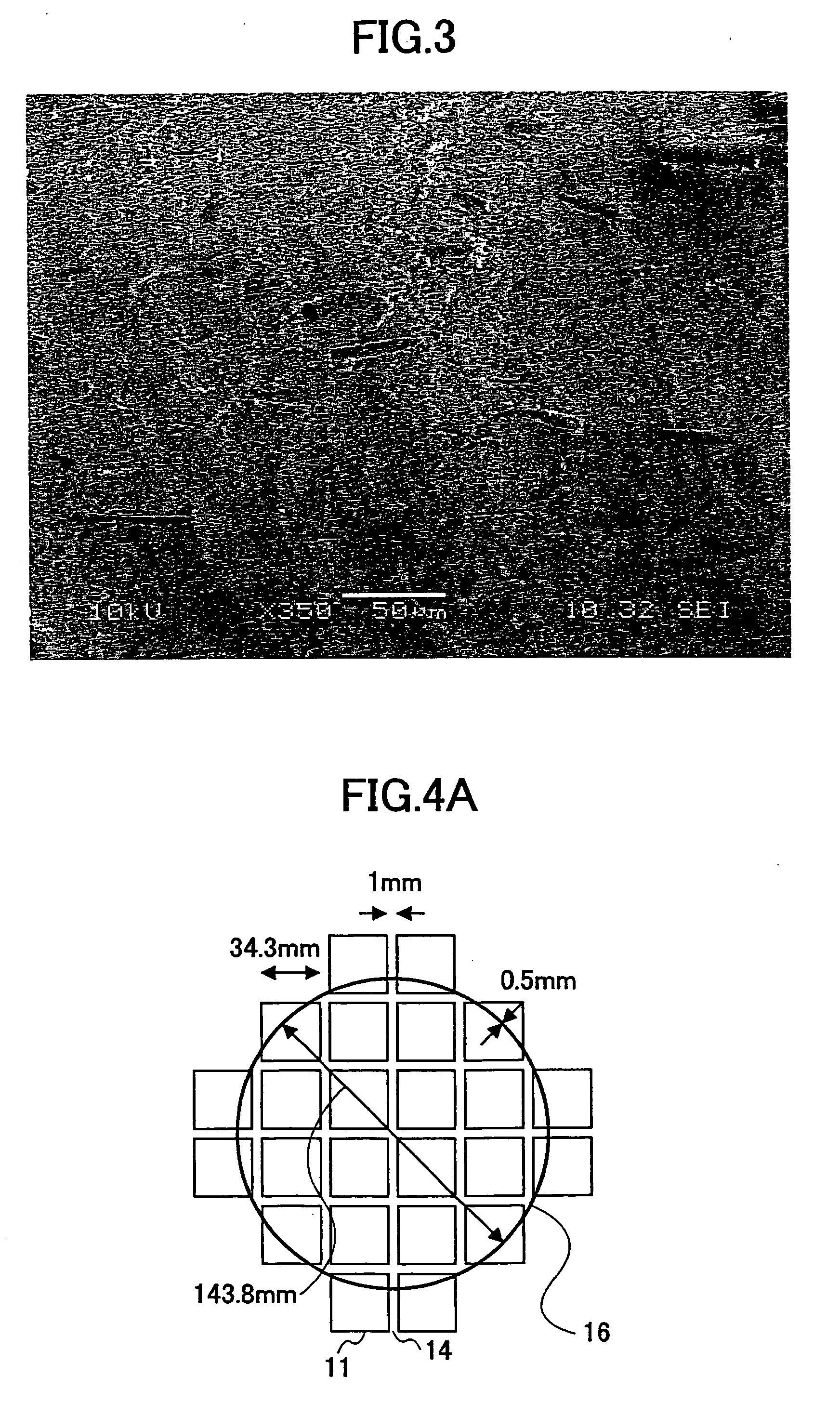
[0100] Honeycomb structures 10 were fabricated in the same way as in the first example with the shapes of the honeycomb units to be those displayed in Table 1. Specifically, FIG. 4B, FIG. 4C, and FIG. 4D show honeycomb structures 10 of comparative example 1, example 2, and reference example 1, and FIG. 5A, FIG. 5B, and FIG. 5C show honeycomb structures 10 of example 3 and comparative examples 2, 3.
[0101] In the comparative example 3, the honeycomb structures 10 is formed integrally, hence, the bonding step and the cutting step were not performed.
examples 4-6
, COMPARATIVE EXAMPLES 4, 5
[0102] Honeycomb structures 10 were fabricated in the same way as in the first example with the surface roughness Ra to be the values shown in Table 1. The shapes of the honeycomb structures 10 of examples 4-6 and comparative examples 4, 5 are the same as that shown in FIG. 4A.
PUM
Abstract
A honeycomb structure is disclosed that includes plural honeycomb units bonded together by using a sealing material layer, each of the honeycomb units including plural through-holes separated by plural partition walls and provided in parallel along a longitudinal direction of the honeycomb units, wherein a surface roughness Ra of an outer surface of the honeycomb structure is greater than or equal to about 1 μm and less than or equal to about 50 μm, each of the honeycomb units includes at least ceramic particles, and inorganic fibers and / or whisker, and an area of a cross section of one of the honeycomb units perpendicular to the longitudinal direction of the one of the honeycomb units is greater than or equal to about 5 cm2 and less than or equal to about 50 cm2.
Description
BACKGROUND OF THE INVENTION [0001] 1. Field of the Invention [0002] The present invention relates to a honeycomb structure. [0003] 2. Description of the Related Art [0004] Generally, a honeycomb catalyst, which is used for conversion of exhaust gas from vehicles, is fabricated by disposing materials of a high specific surface-to area like active alumina and catalysts like platinum on the surface of a monolithic cordierite-based honeycomb structure having a low thermal expansion characteristic. In addition, the honeycomb catalyst carries an alkali-earth metal like barium to act as an occlusion-type NOx catalyst for a processingNOx in an oxygen-rich atmosphere, such as atmospheres in a lean-burn engine or a Diesel engine. [0005] In order to further improve conversion performance, it is necessary to increase the contact probability between the exhaust gas and the catalyst element and the NOxocclusion agent as well. For this purpose, it is required to increase the specific surface-to ...
Claims
Application Information
Patent Timeline
Application Date:The date an application was filed.
Publication Date:The date a patent or application was officially published.
First Publication Date:The earliest publication date of a patent with the same application number.
Issue Date:Publication date of the patent grant document.
PCT Entry Date:The Entry date of PCT National Phase.
Estimated Expiry Date:The statutory expiry date of a patent right according to the Patent Law, and it is the longest term of protection that the patent right can achieve without the termination of the patent right due to other reasons(Term extension factor has been taken into account ).
Invalid Date:Actual expiry date is based on effective date or publication date of legal transaction data of invalid patent.

