
Electroosmotic flow controller

a flow controller and electroosmosis technology, applied in the direction of diaphragms, ratio control, electrolysis, etc., can solve the problems of inability to maintain precise flow rates in the face of changing heads, introduce additional imprecision and dead space into flow-controlled devices, etc., to achieve rapid and accurate flow control

Active Publication Date: 2007-01-04
SCIEX
View PDF54 Cites 49 Cited by
  • Summary
  • Abstract
  • Description
  • Claims
  • Application Information

AI Technical Summary

Benefits of technology

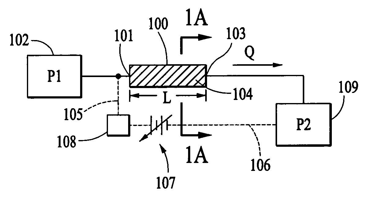
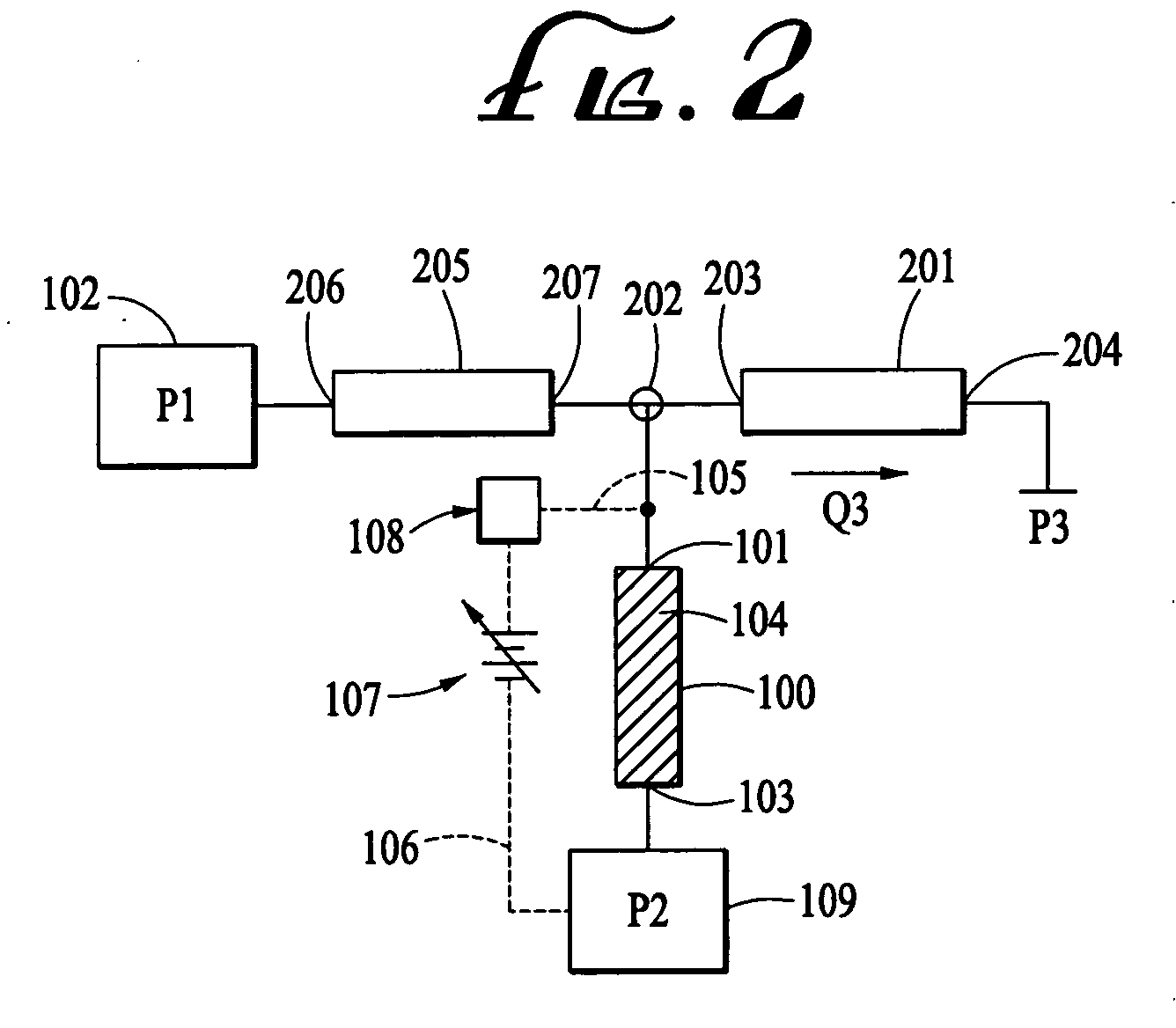
[0013] The present invention provides an electroosmotic flow controller capable of controlling fluid flow through a combination of electroosmotic and pressure-driven flows. The inventors have recognized that by adding an electroosmotic flow component to a pressure-driven flow component, one may effect rapid and accurate flow control over a wide range of flow rates. Devices embodying the invention may be made with few or no moving parts and are compatible with most solvents. They may be readily fabricated as true microscale devices. Devices embodying the present invention may be used to reliably and accurately correct for over pressurizations, pressure waves, and flow inaccuracies caused by the use of oversized pumps in microseparations. The devices can be driven by virtually any type of pressure generator, including high pressure syringe pumps, hand pumps, or air-driven systems.

Problems solved by technology

Prior art flow controllers tend to suffer from a variety of shortcomings.
In high flow and in low flow applications, prior art flow controllers have difficulty in maintaining precise flow rates in the face of changing head pressures, such as those generated by pumping devices.
In addition, mechanical feedback loops used to control flow rates through flow controllers often introduce additional imprecision and dead space into flow-controlled devices.
Currently, chemical separations and purification represent severe bottlenecks in many biotechnology and drug discovery applications.
Traditional scale separation systems are not compatible with the speed and small sample sizes typically required for high throughput analytical techniques.
These analytical tasks are in many respects more challenging than genome sequencing efforts.
Therefore, the reliable microseparation techniques developed for gene sequencing are inadequate for protein analysis.
Many problems exist with 2D gels, however.
Inter- and intra-laboratory reproducibility is notoriously poor.
The analysis is time consuming, the 2D separation typically taking 1-2 days.
Given the high cost and large size of conventional HPLC systems, it is impractical to run more than a few systems in parallel.
Also, the speed at which a separation can be done is limited by the large sample requirements of the system.
However, most currently available micro HPLC systems are simply large scale systems outfitted with flow reducers and dampers, and as such are not truly microscale flow devices.
The macroscale high pressure pumps used in these systems are often unable to meter fluid flow with sufficient accuracy to generate reliable and rapid gradients, which are critical to reproducible HPLC analysis.

Method used


Image

  • Electroosmotic flow controller
  • Electroosmotic flow controller
  • Electroosmotic flow controller

Examples


Embodiment Construction

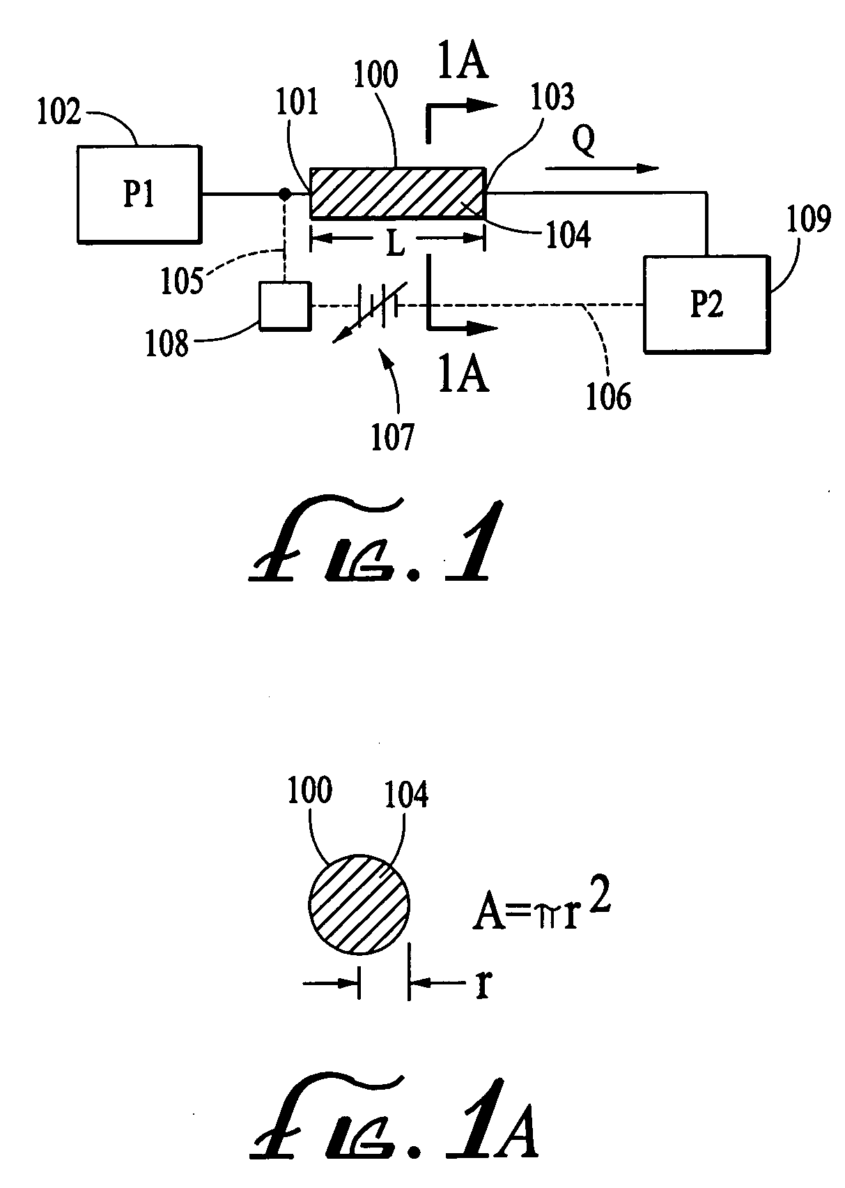
[0052] Electroosmotic flow in open channels and in porous media is a well-know phenomena and has been the subject of many experimental and theoretical studies. When a liquid (e.g. water) is in contact with a dielectric solid (e.g. glass, silica, many plastics and ceramics) the natural electrochemistry of the interaction produces a thin layer of net charge density in the fluid that is localized to the liquid-solid interface. An electrical field applied so as to produce a component tangential to this interface will produce a Lorentz force on this net charge density. This net force will cause a motion of the net charge and this motion will be imparted by viscous action to the remaining neutral fluid. Thus in a channel packed with a porous dielectric material that is filled or saturated by an appropriate liquid, a potential difference ΔV applied end-to-end will produce what is known as an electroosmotic flow of the liquid. This electroosmotic flow may compete with or even dominate the f...


PUM

PropertyMeasurementUnit
diameteraaaaaaaaaa
diameteraaaaaaaaaa
timeaaaaaaaaaa

Abstract

Electroosmotic flow controllers and methods of fluid flow control are described. The invention uses an electroosmotically generated flow component in conjunction with a pressure driven flow component to modulate fluid flow. The devices and methods of the invention may include salt bridges for making electrical connection between a power supply and a channel filled with a porous dielectric material and a fluid. Embodiments including flow controllers and flow splitters are described as is their use in a variety of fluid handling applications.

Description

CROSS-REFERENCE TO RELATED APPLICATIONS [0001] This application is a divisional of U.S. patent application Ser. No. 09 / 942,884, filed on Aug. 29, 2001, which claims the benefit of U.S. Provisional Patent Application 60 / 298,147, filed Jun. 13, 2001, the entire contents of which are hereby incorporated herein by reference in their entirety.BACKGROUND OF THE INVENTION [0002] The invention pertains to the fields of fluid handling and electroosmosis. More particularly, the invention pertains to electroosmotic flow controllers. [0003] Flow controllers are used to manage the flow of fluids through conduits. Traditionally, control of fluid volume and or fluid composition by flow controllers is accomplished by combinations of pumps and valves. In some applications, flow controllers are used to control fluid flows on the order of many milliliters or more per minute, while in other applications, the fluid flow rates are orders of magnitude smaller. Prior art flow controllers tend to suffer fro...

Claims


Application Information

Patent Timeline
Patent Type & Authority Applications(United States)
IPC IPC(8): G01N27/00C07K1/26B01D61/56G01N30/32G05D7/06G05D11/13
CPCB01D61/56G01N30/32G01N2030/324G01N2030/326G05D7/0694G05D11/132G01N30/34G01N2030/285Y10T137/85986Y10T137/85978Y10T137/86027
Inventor PAUL, PHILLIP H.ARNOLD, DON WESLEYBAILEY, CHRISTOPHER G.
Owner SCIEX
Learn More