Active embolization device
a technology of embolization device and active electrode, which is applied in the direction of surgery, coating, other domestic articles, etc., can solve the problems of coil compaction, increase the risk of aneurysm rupture,
- Summary
- Abstract
- Description
- Claims
- Application Information
AI Technical Summary
Benefits of technology
Problems solved by technology
Method used
Image
Examples
example 1
Polymer Solution Preparation
[0049] A 1% w / w solution of epsilon-caprolactone / glycolide copolymer in 1,4-dioxane was prepared as follows. 1.5 grams of 36 / 64 poly(epsilon-caprolactone-glycolic acid) copolymer, obtained from American Polymer Incorporation (American Polymer Inc., Birmingham, Ala.) was added to 148.8 grams of 1,4-dioxane (Fisher Scientific, Raritan, N.J.) in a 250 milliliter Erlenmeyer screwed cap flask. The mixture was stirred for 4 hours in 60° C. water bath set on a temperature controlled heating plate. The polymer solution was filtered through an extra coarse thimble filter to remove any undissolved solids.
example 2
Making 36 / 64 PCL / PGA Foamed Coils Using Freeze-Dry Method
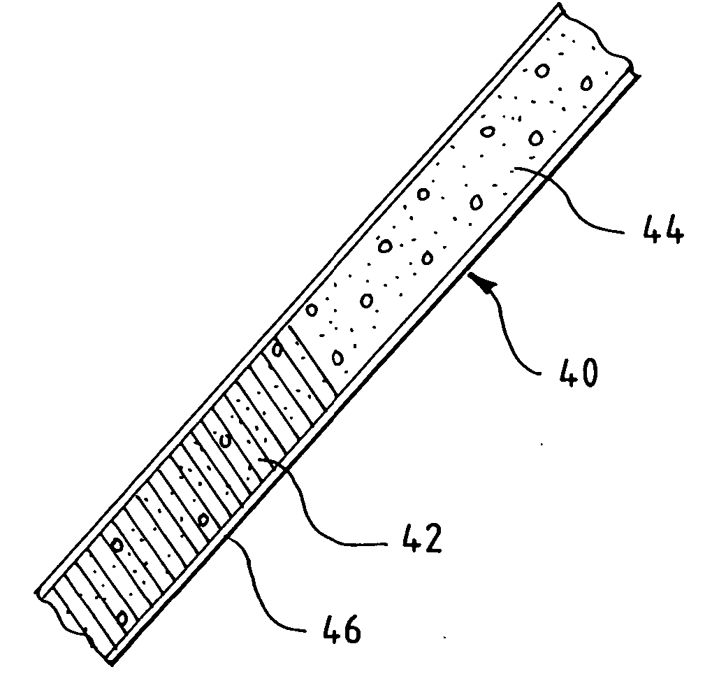
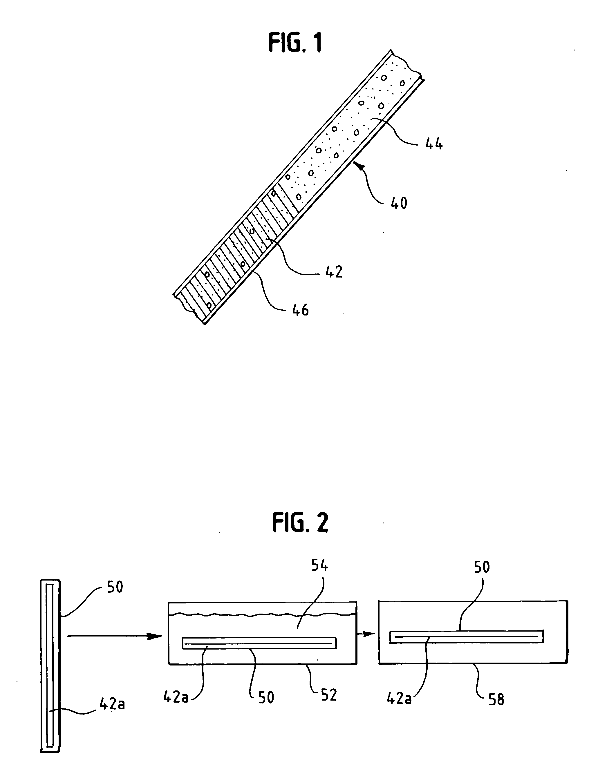
[0050] A 10-cm embolic coil was inserted in a polytetrafluoroethylene (PTFE) tubing (0.015″ ID, ZEUS Industrial products, Inc. Orangeburg, S.C.) that was 2 centimeters longer that the coil. The tube served as a mold. The tube mold containing the coil was filled with the 1% w / w solution of the epsilon-caprolactone / glycolide copolymer in 1,4-dioxane described in Example 1, using a glass syringe with a 30G needle attached. The tube mold containing the coil and solution was sonicated for approximately 5 minutes in a sonication bath (BRANSON, Model 3210R-DTH, Danbury, Conn.) to ensure the solution got into the inter-diameter of the coil, between the coils and into the coil lumen. Bubbles generated during sonication were replaced with fresh polymer solution. Then, the tube mold was frozen in liquid nitrogen for about five minutes, and placed on a pre-cooled (−17° C.) shelf of a freeze-dryer (lyophilization unit) (FTS Systems, Model...
example 3
Fibronectin Absorption Experiment
[0051] A 4-cm foam-embedded coil from Example 2 was cut into about 4-mm segments. Coil segments were then placed in to Siliconized Eppendorf tubes. The coil segments were wet with 0.5 milliliters of 70% ethanol, and then washed twice with 1 milliliter of phosphate buffered saline (PBS). The coil segments were incubated with 100 μl of fibronectin probe solution. The solution was purchased from Sigma Chemical Co. (St. Louis, Mo.). and was radio labeled by iodine 125 at Lofstrand Labs Limited (Gaithersburg, Md.). The incubation was for 1 hour at 37° C. Afterwards, the incubated coil segments were washed three times with 1 milliliter 0.1% Triton in PBS. The coil segments were transferred to a scintillation vial and the radioactivity of the samples was counted. Absorption of fibronectin on foamed coils of Example 2 was about 3 fold higher than on the bare coils under similar treatment.
PUM
| Property | Measurement | Unit |
|---|---|---|
| diameter | aaaaa | aaaaa |
| diameter | aaaaa | aaaaa |
| diameter | aaaaa | aaaaa |
Abstract
Description
Claims
Application Information
 - R&D
- Intellectual Property
- Life Sciences
- Materials
- Tech Scout
- Unparalleled Data Quality
- Higher Quality Content
- 60% Fewer Hallucinations
Browse by: Latest US Patents, China's latest patents, Technical Efficacy Thesaurus, Application Domain, Technology Topic, Popular Technical Reports.
© 2025 PatSnap. All rights reserved.Legal|Privacy policy|Modern Slavery Act Transparency Statement|Sitemap|About US| Contact US: help@patsnap.com


