Sealing arrangement for a fuel cell stack and process for the production of such a sealing arrangement

a technology of sealing arrangement and fuel cell, which is applied in the direction of cell components, final product manufacturing, sustainable manufacturing/processing, etc., can solve the problems of low stability of sealing materials usually used, ceramic coatings can contain pores and/or gaps, and the electrical resistance is no longer sufficiently high, etc., to achieve adequate mechanical strength, high operating temperature, and adequate electrical insulation

Inactive Publication Date: 2007-01-04
ELRINGKLINGER AG
View PDF7 Cites 34 Cited by
  • Summary
  • Abstract
  • Description
  • Claims
  • Application Information

AI Technical Summary

Benefits of technology

[0008] The object forming the basis of the present invention is to provide a sealing arrangement for a fuel cell stack of the aforementioned type, which also has an adequate electrical insulation effect and an adequate mechanical strength at a high operating temperature of the fuel cell stack.

Problems solved by technology

In the case of some of the sealing materials usually used, the electrical resistance is no longer sufficiently high at the operating temperature of a high-temperature fuel cell unit (in the range of approximately 800° C. to approximately 900° C.) to attain a satisfactory insulation effect.
Moreover, some of the sealing materials usually used have only a low stability with respect to the temperature changes (between operating and resting phases) that frequently arise with a high-temperature fuel cell unit.
However, the insulating ceramic coating can contain pores and / or gaps, in particular when the ceramic coating is applied by thermal spraying to a metal part to be insulated.
Depending on the capillary activity of the solder used, the solder can penetrate into the pores or gaps present in the ceramic coating and cause a short-circuit.

Method used


Image

  • Sealing arrangement for a fuel cell stack and process for the production of such a sealing arrangement
  • Sealing arrangement for a fuel cell stack and process for the production of such a sealing arrangement
  • Sealing arrangement for a fuel cell stack and process for the production of such a sealing arrangement

Examples


Embodiment Construction

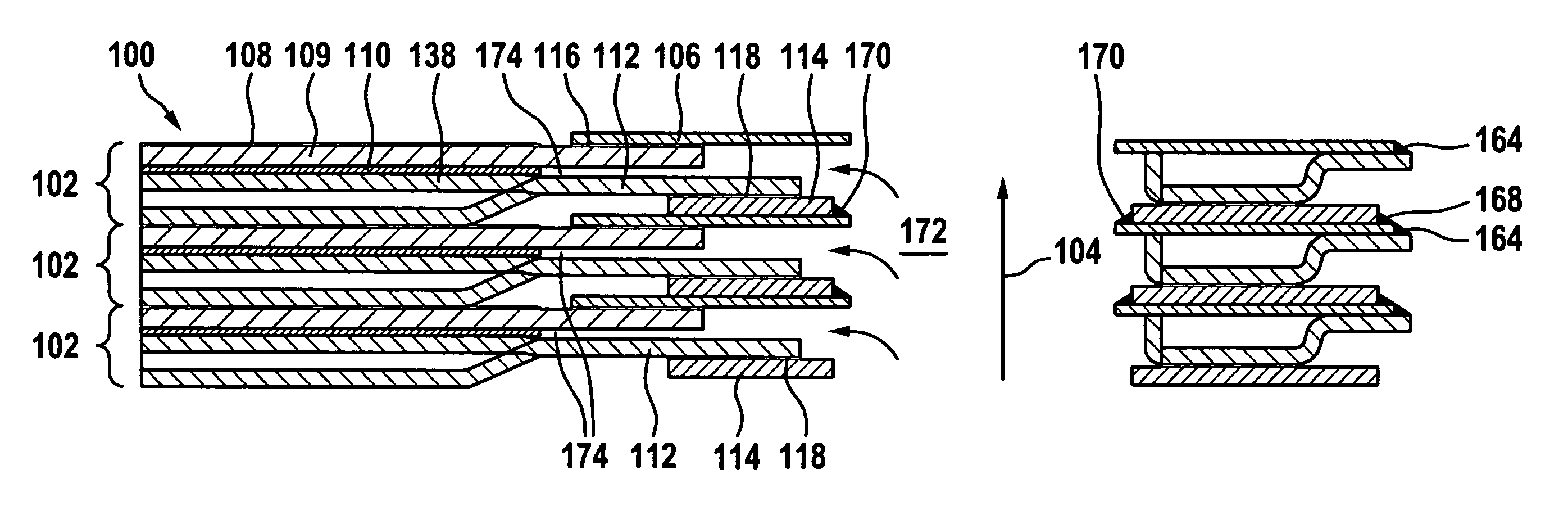
[0080] A fuel cell stack shown in FIGS. 5 to 16, given the overall reference 100, comprises a plurality of fuel cell units 102, each having the same structure, which are stacked on top of one another in a vertical stacking direction 104.

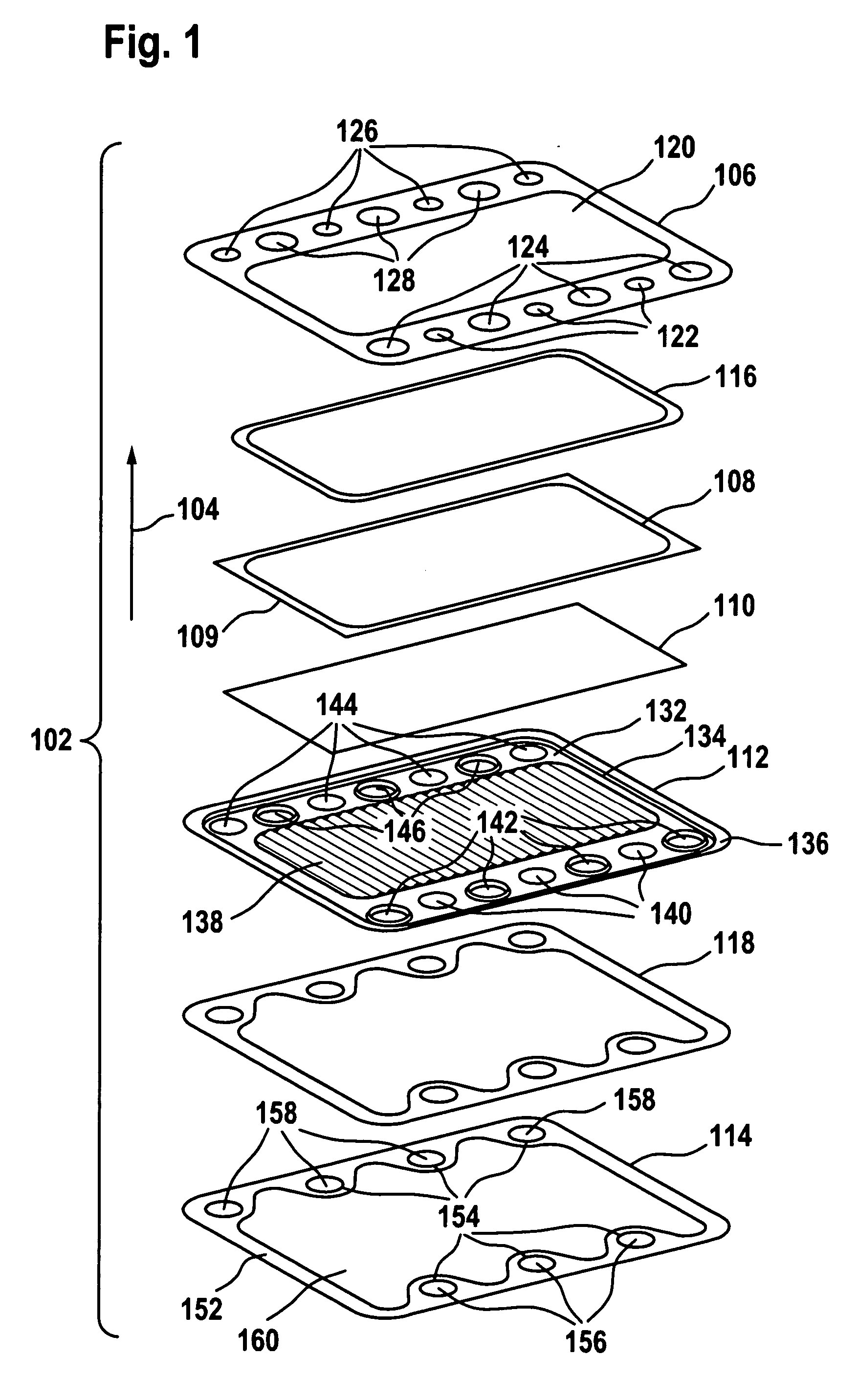
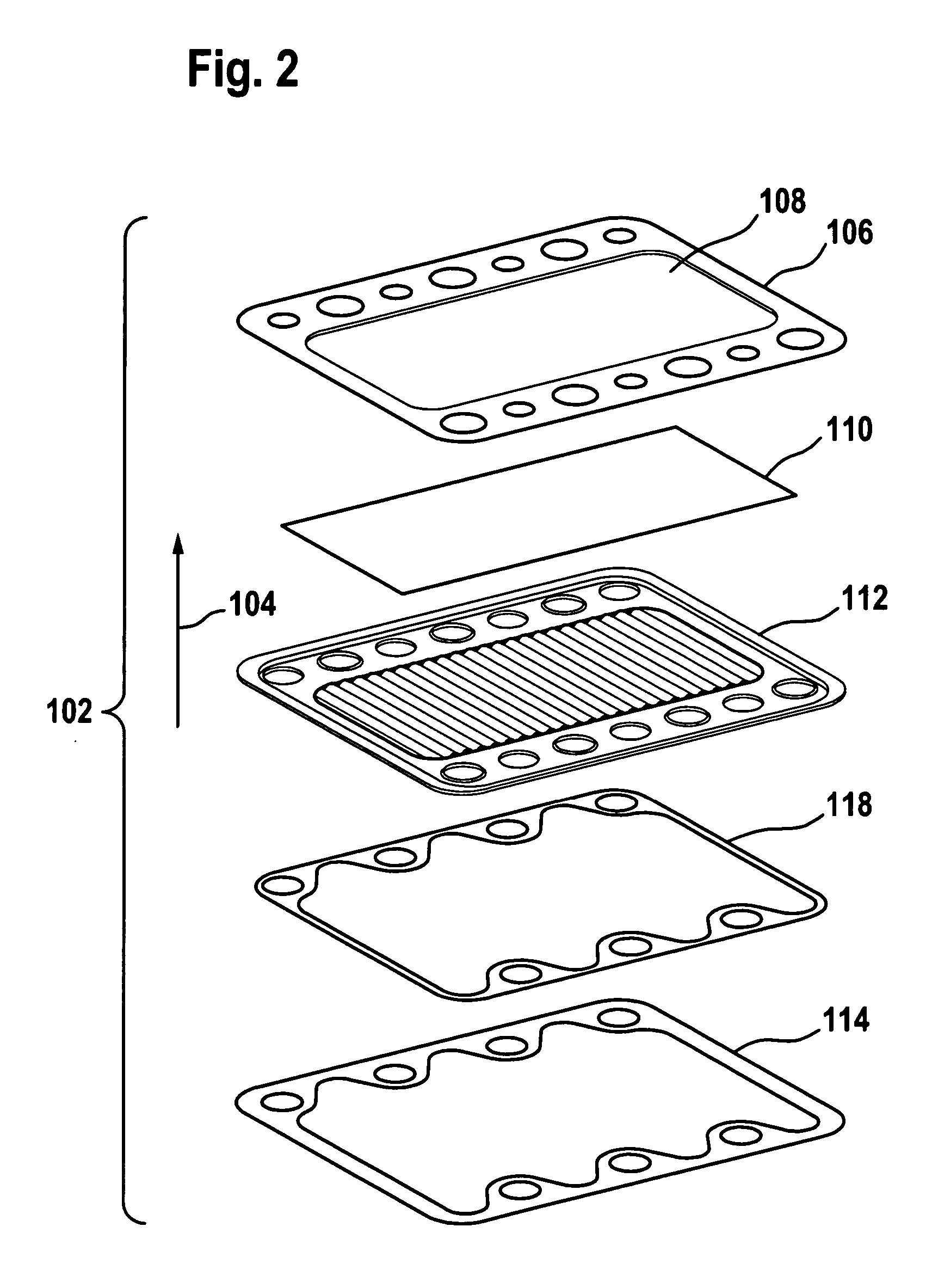
[0081] Each of the fuel cell units 102 comprises the components shown individually in FIG. 1, namely a housing upper part 106, a cathode-electrolyte-anode unit (CEA unit) 108 on a substrate 109, a contact material 110, a housing lower part 112 and an intermediate element 114.

[0082]FIG. 1 additionally shows a solder layer 116 for soldering the substrate 109 to the housing upper part 106 and a sealing arrangement 118 for connecting the intermediate element 114 to the housing lower part 112 in a gastight and electrically insulating manner.

[0083] The housing upper part 106 is configured as a substantially rectangular and substantially plane sheet metal plate, which is provided with a substantially rectangular central passage 120, through which in the ...


PUM

PropertyMeasurementUnit
thicknessaaaaaaaaaa
thicknessaaaaaaaaaa
thicknessaaaaaaaaaa

Abstract

In order to provide a sealing arrangement for a fuel cell stack, which comprises a plurality of fuel cell units, which are arranged consecutively in a stacking direction, wherein the sealing arrangement has an electrical insulation effect, and which also has an adequate electrical insulation effect and an adequate mechanical strength at a high operating temperature of the fuel cell stack, it is proposed that the sealing arrangement comprises at least one ceramic-metal layer formed from a mixture of a ceramic material and a metal material.

Description

RELATED APPLICATION [0001] The present disclosure relates to the subject matter disclosed in German Patent Application No. 10 2005 029 762.5 of Jun. 20, 2005, the entire specification of which is incorporated herein by reference. FIELD OF THE DISCLOSURE [0002] The present invention relates to a sealing arrangement for a fuel cell stack, which comprises a plurality of fuel cell units, which are arranged consecutively in a stacking direction, wherein the sealing arrangement has an electrical insulation effect. BACKGROUND [0003] For adjustment of the desired operating voltage, fuel cell units are arranged one on top of the other in the required number in order to thus form a fuel cell stack. To prevent an electrical short-circuit, the housings of fuel cell units arranged consecutively in the fuel cell stack are electrically insulated from one another. It is additionally necessary to separate the fuel gas ducts of the fuel cell stack from the oxidising agent chambers of the fuel cell un...

Claims


Application Information

Patent Timeline
Patent Type & Authority Applications(United States)
IPC IPC(8): H01M2/08F16J15/10B05D5/12
CPCC23C4/00C23C4/02C23C4/06Y02E60/50H01M8/0282H01M8/0286C23C4/18Y02P70/50
Inventor ZERFASS, HANS-RAINERHENNE, RUDOLFARNOLD, JOHANNES
Owner ELRINGKLINGER AG
Why Eureka
Try Eureka