

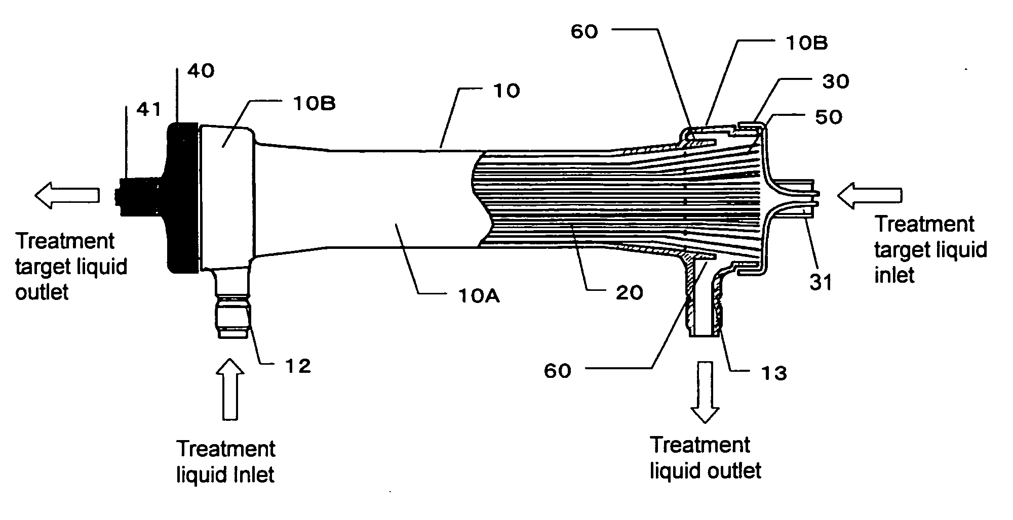
Body fluid treating device of hollow fiber membrane type
a treatment device and hollow fiber membrane technology, applied in the field of new hemodialyzers, can solve the problems of insufficient substance removal performance of conventional hemodialyzers, complex technology is required, and inability to obtain sufficient substance removal performance, so as to achieve the effect of improving the substance removal performance of hemodialyzers, preventing the effect of dropping or falling or a water stream, and significantly improving the performance of substance removal
- Summary
- Abstract
- Description
- Claims
- Application Information
AI Technical Summary
Benefits of technology
Problems solved by technology
Method used
Image

Examples
example 1
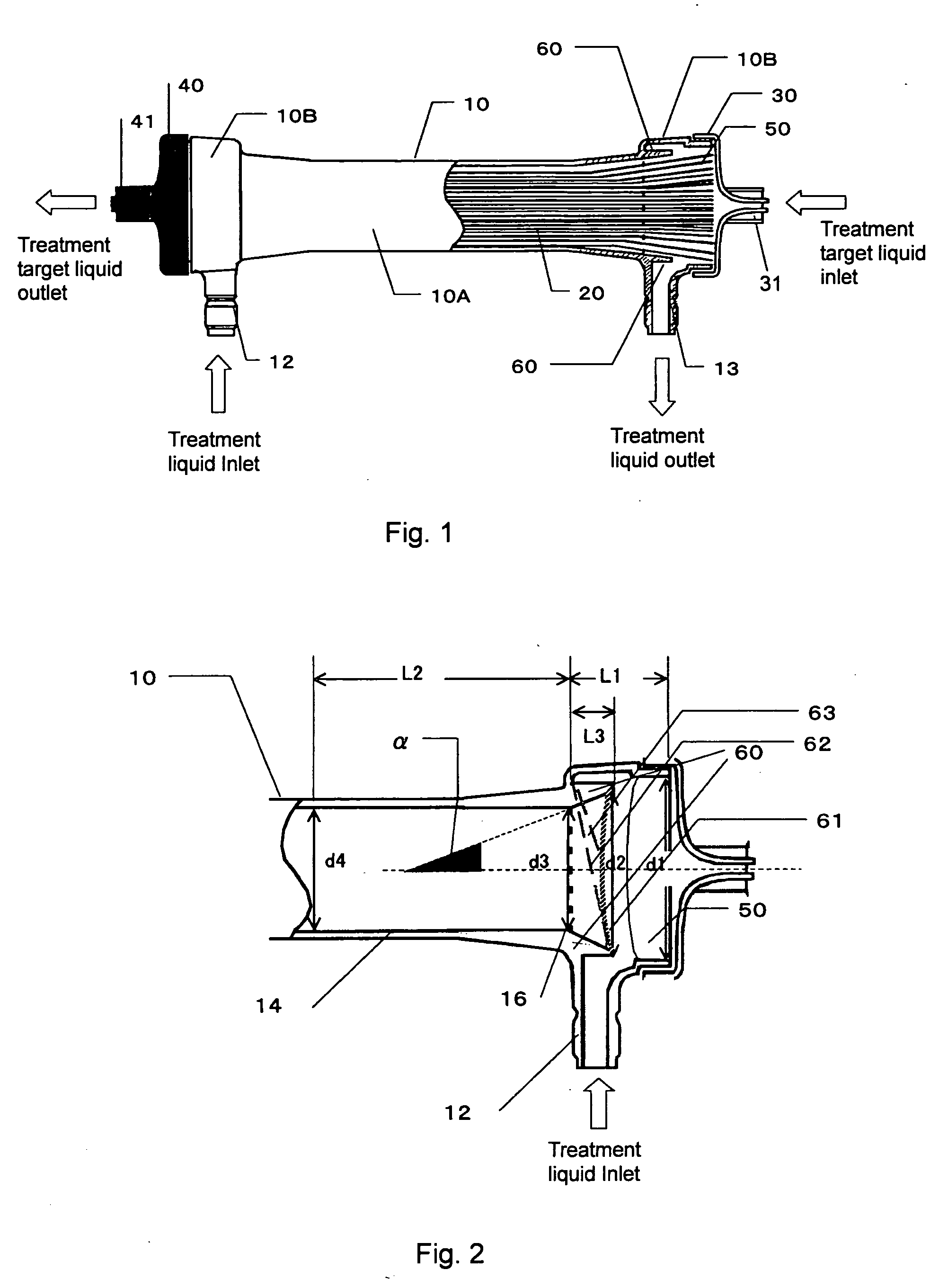
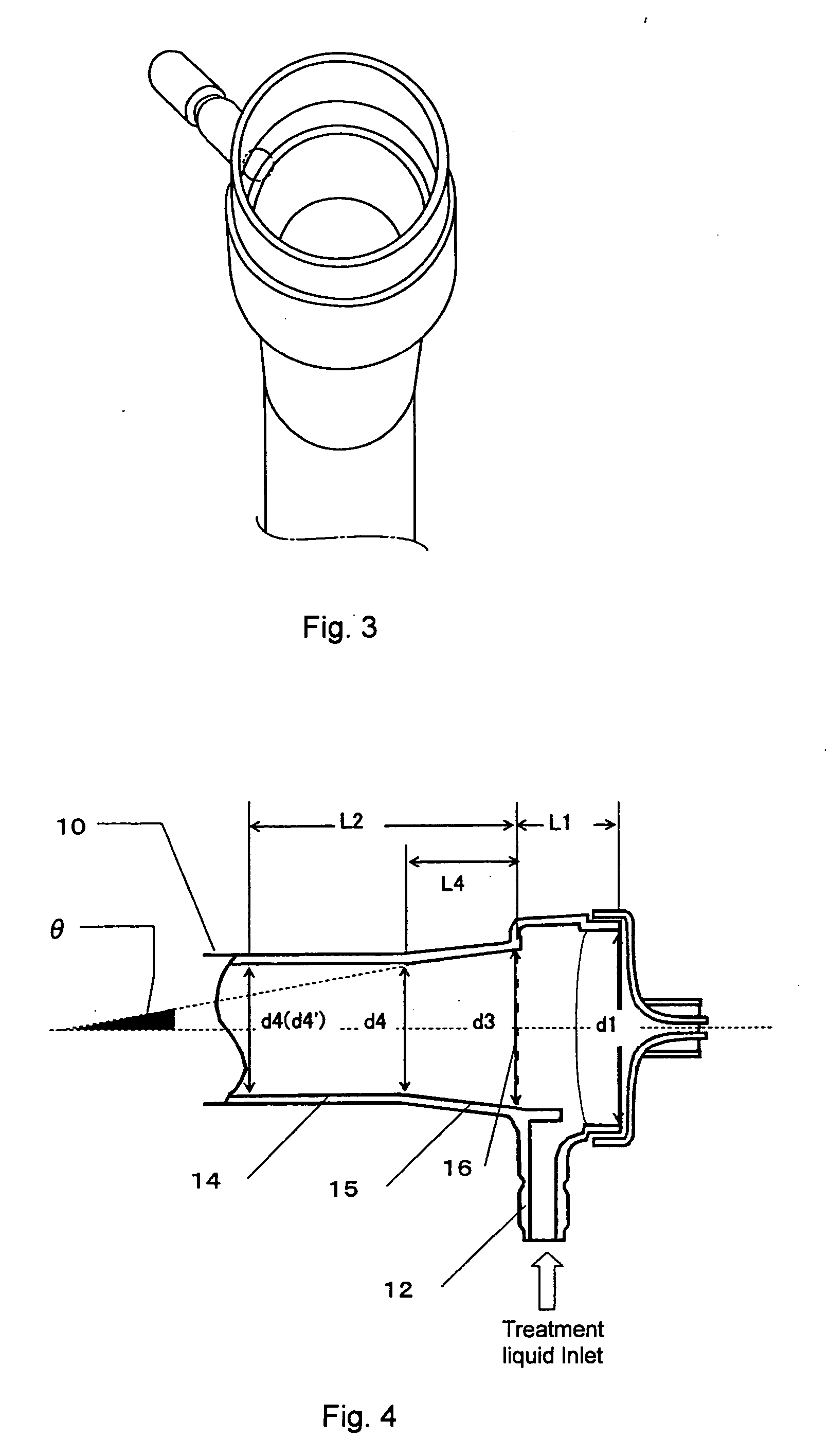
[0086] A hollow fiber membrane bundle was formed by bundling 9200 hydrophilized polysulfone hollow fiber membranes (inner diameter: 200 μm, thickness: 45 μm, water permeablity: 300 ml / m2·hr·mmHg, aqueous mass transfer coefficient of urea: 9.0×10⁻⁴ cm / sec, aqueous mass transfer coefficient of vitamin B 12: 3.1×10⁻⁴ cm / sec) obtained from polysulfone and polyvinylpyrrolidone by using a known wet spinning method. The hollow fiber membrane bundle was placed in a tubular housing so that the membrane area might be 1.5 m2. Both ends of the hollow fiber membrane bundle was potted with polyurethane resin to form a hollow fiber membrane type fluid treatment device. The inclination angle α of the baffle plate of the housing was made into 11.9°. The remainder of the above-defined values is also collectively shown in Table 1.
[0087] The clearance and the drop leakage occurrence rate of the resulting hollow fiber membrane type fluid treatment device are shown in Table 1.
example 2
[0088] A hollow fiber membrane type fluid treatment device having a membrane area of 1.5 m2 was formed in the same manner as in Example 1, except for using a baffle plate having the angle α of 11.9° and an edge curving along the outer circumference inside the resin layer as indicated by 61 shown in FIG. 4. In this case, since the height L3 of the baffle plate and the inner diameter d2 at the edge are not constant in the circumferential direction of the housing, data shown in the table is given as a reference value.
[0089] The clearance and the drop leakage occurrence rate of the resulting hollow fiber membrane type fluid treatment device are shown in Table 1.
example 3
[0090] A hollow fiber membrane type fluid treatment device having a membrane area of 1.5 m2 was formed in the same manner as in Example 1 except for using a tubular housing having an angle α of 1.2°. The clearance and the drop leakage occurrence rate of the resulting hollow fiber membrane type fluid treatment device are shown in Table 1.
PUM
| Property | Measurement | Unit |
|---|---|---|
| Angle | aaaaa | aaaaa |
| Angle | aaaaa | aaaaa |
| Volumetric flow rate | aaaaa | aaaaa |
Abstract
Description
Claims
Application Information