Electromagnetic fuel injector

a fuel injector and electromagnet technology, applied in the direction of machines/engines, magnetic bodies, electric control, etc., can solve the problems of reduced life, rationalization, and intensive production of these terminals and other parts, and achieve compact structure, cost reduction, and performance improvement

Inactive Publication Date: 2007-01-11
HITACHI LTD +1
View PDF20 Cites 14 Cited by
  • Summary
  • Abstract
  • Description
  • Claims
  • Application Information

AI Technical Summary

Benefits of technology

[0013] An object of the present invention is to provide an injector in which these problems are solved and the heat radiation property of the coil of the injector accompanied by the performance improvement is raised, and which can entirely withstand the environment of the intense heat and assures its long life and moreover can intend to achieve the compact structure and the cost reduction.

Problems solved by technology

Particularly an intense heat of the coil under the violent state of the high temperature circumstances such as the inside of the engine room deteriorates the state of the insulation film and the bobbin of the coil and results in the reduction of the life.
Therefore the problems remain in that how these terminals and other parts are made intensive and rationalized and the injector is realized at compact structure and low cost.

Method used


Image

  • Electromagnetic fuel injector
  • Electromagnetic fuel injector
  • Electromagnetic fuel injector

Examples


Embodiment Construction

[0031] An embodiment of the present invention will be described based on the drawings.

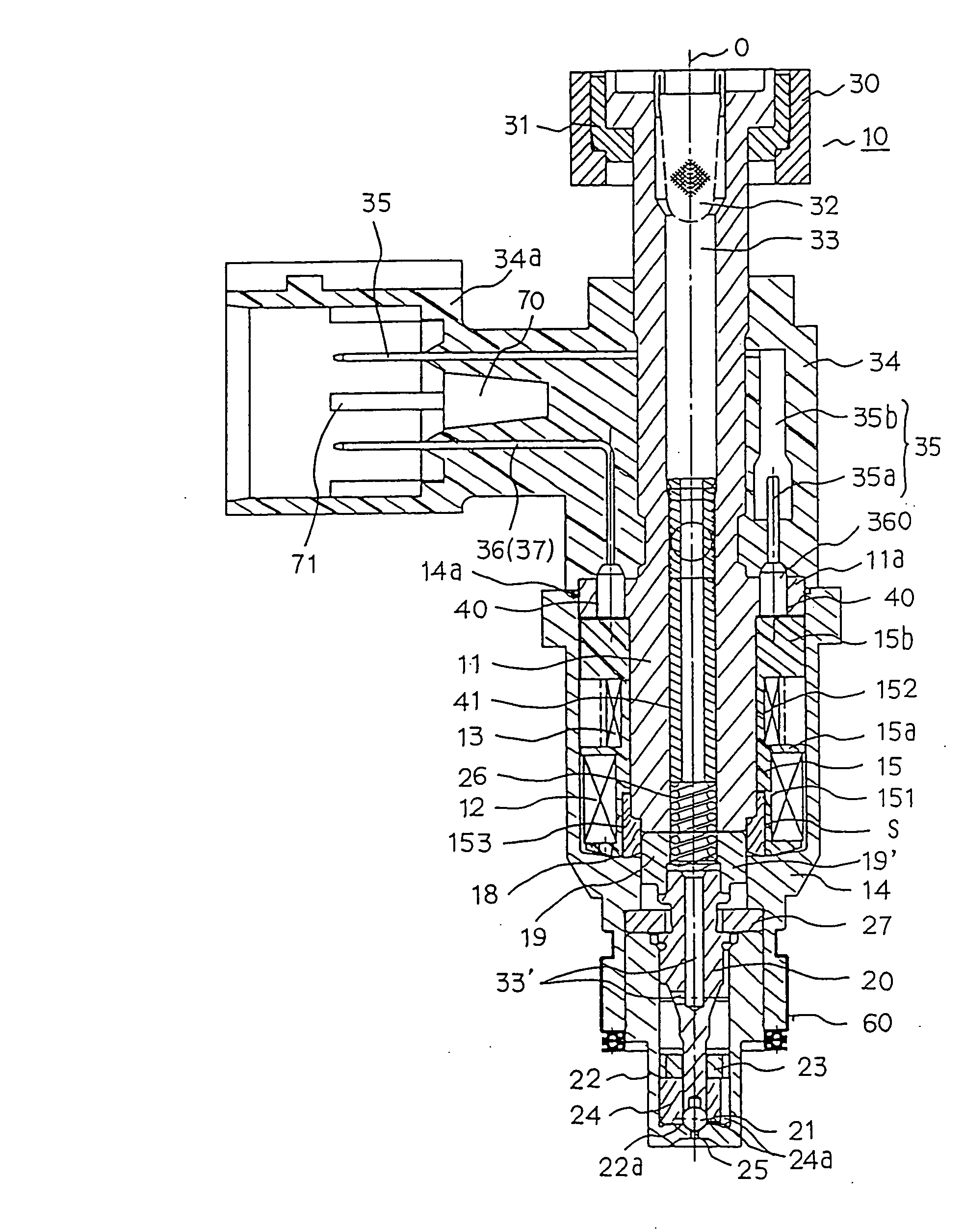
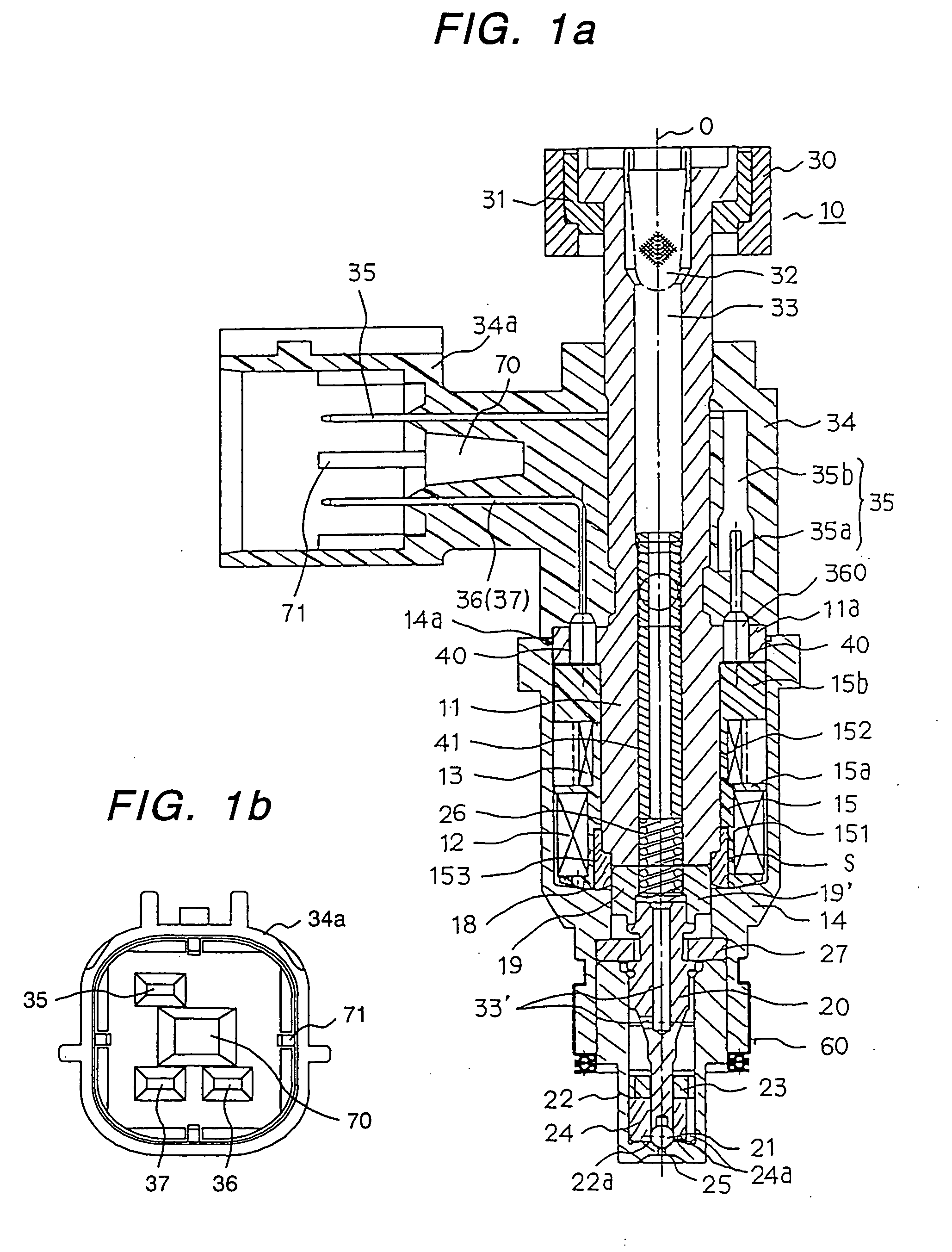
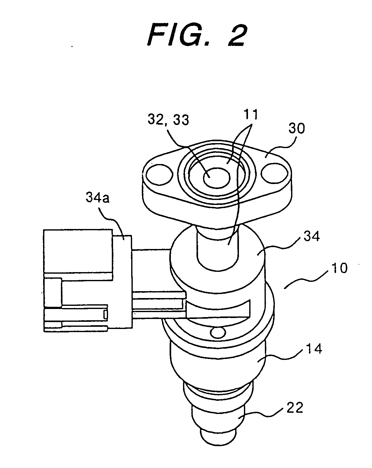
[0032] At first, the structure of an injector 10 in the embodiment will be described using FIG. 1.

[0033] The injector 10 is constituted by a stationary core 11, electromagnetic coils 12, 13, a yoke 14, a movable unit (also referred to as a movable core, a plunger or the like) 19 having a valve element 21, a nozzle 22, a return spring 26, an external resin mold 34 with a connector 34a and the like.

[0034] The movable unit 19 in this embodiment comprises a cylindrical movable core 19′ having magnetism and a valve rod 20 coupled integrally.

[0035] In the inside of the cylindrical yoke 14 being a body of the injector, the stationary core (center core) 11, and the first coil 12 and the second coil 13 wound on a bobbin 15 are arranged from the center position toward the outside. The structure of the bobbin 15 and details of the coils 12, 13 will be described later.

[0036] The stationary core 11 is form...


PUM


Abstract

In an electromagnetic fuel injector of an internal combustion engine, an electromagnetic coil for valve driving is to be wound on a bobbin, and the bobbin is constituted by a synthetic resin containing a filler having good heat conductivity. For example, the bobbin with the coil to be wound thereon is constituted by PPS containing iron oxide and / or alumina as a filler. Two types of electromagnetic coils different in characteristics are provided in the fuel injector. These coils are wound separately on one bobbin in an axial direction. Among them, one coil (hereinafter referred to as “first coil”) has a winding region near a movable unit with a valve element being the object of magnetic suction, and other-coil (hereinafter referred to as “second coil”) has a winding region away from the movable unit. The bobbin has a step difference of the outer diameter so that the bobbin outer diameter in the region with the second coil to be wound thereon is smaller than the bobbin outer diameter in the region with the first coil to be wound thereon, and the bobbin inner diameter has a step difference in that the bobbin inner diameter in the region with the first coil to be wound thereon is made large partially so as to secure an annular space to interpose a seal ring therein.

Description

BACKGROUND OF THE INVENTION [0001] 1. Field of the Invention [0002] The present invention relates to an electromagnetic fuel injector for an internal combustion engine. [0003] 2. Description of Related Art [0004] In an electromagnetic fuel injection valve (sometimes called an injection valve), opening and closing operation is performed by controlling an electromagnetic coil in energizing with current and interrupting, and while the valve is opened, a fuel is injected to-a intake air passage, a intake port or a combustion chamber. [0005] As such an injector, a system is put to practical use, where in order to improve rising characteristics while a valve is opened, high voltage is produced by providing a drive circuit with a booster circuit, and while the high voltage is impressed to a coil of the injector, a current control circuit is used and a large current is forced to flow at a short time (for example, JP-A 6-241137). In the system, a battery voltage (for example, 12V) is raised ...

Claims


Application Information

Patent Timeline
Patent Type & Authority Applications(United States)
IPC IPC(8): F16K31/02F02D41/20F02M51/00F02M51/06F02M61/16F02M63/00
CPCF02D41/20F02D2041/2013F02D2041/2079F02M51/005F02M51/0621H01F2007/083F02M51/0675F02M61/165F02M2200/505H01F5/02F02M51/0671
Inventor HAMADA, YASUNAGANAMAIZAWA, YASUO
Owner HITACHI LTD
Why Eureka
Try Eureka