

Electron beam writing apparatus and writing method
- Summary
- Abstract
- Description
- Claims
- Application Information
AI Technical Summary
Benefits of technology
Problems solved by technology
Method used
Image

Examples
embodiment 1
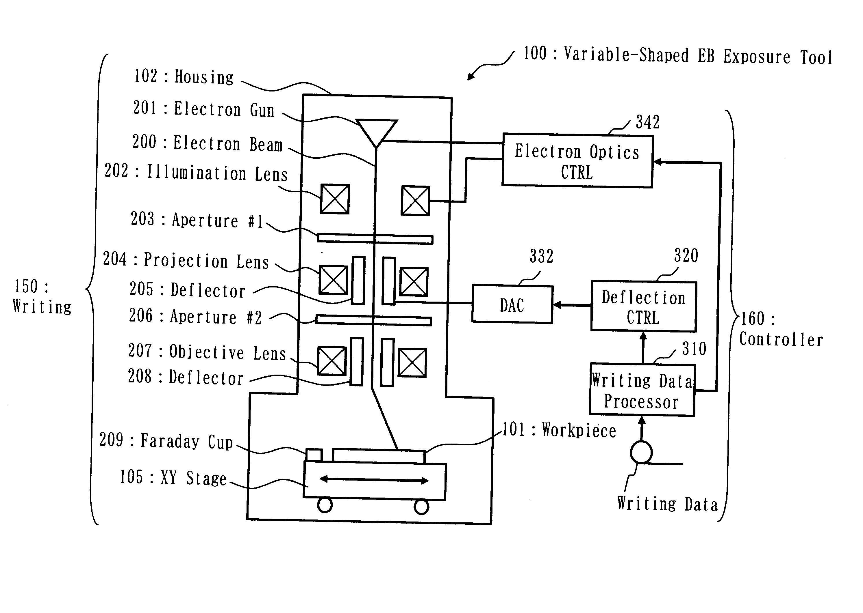
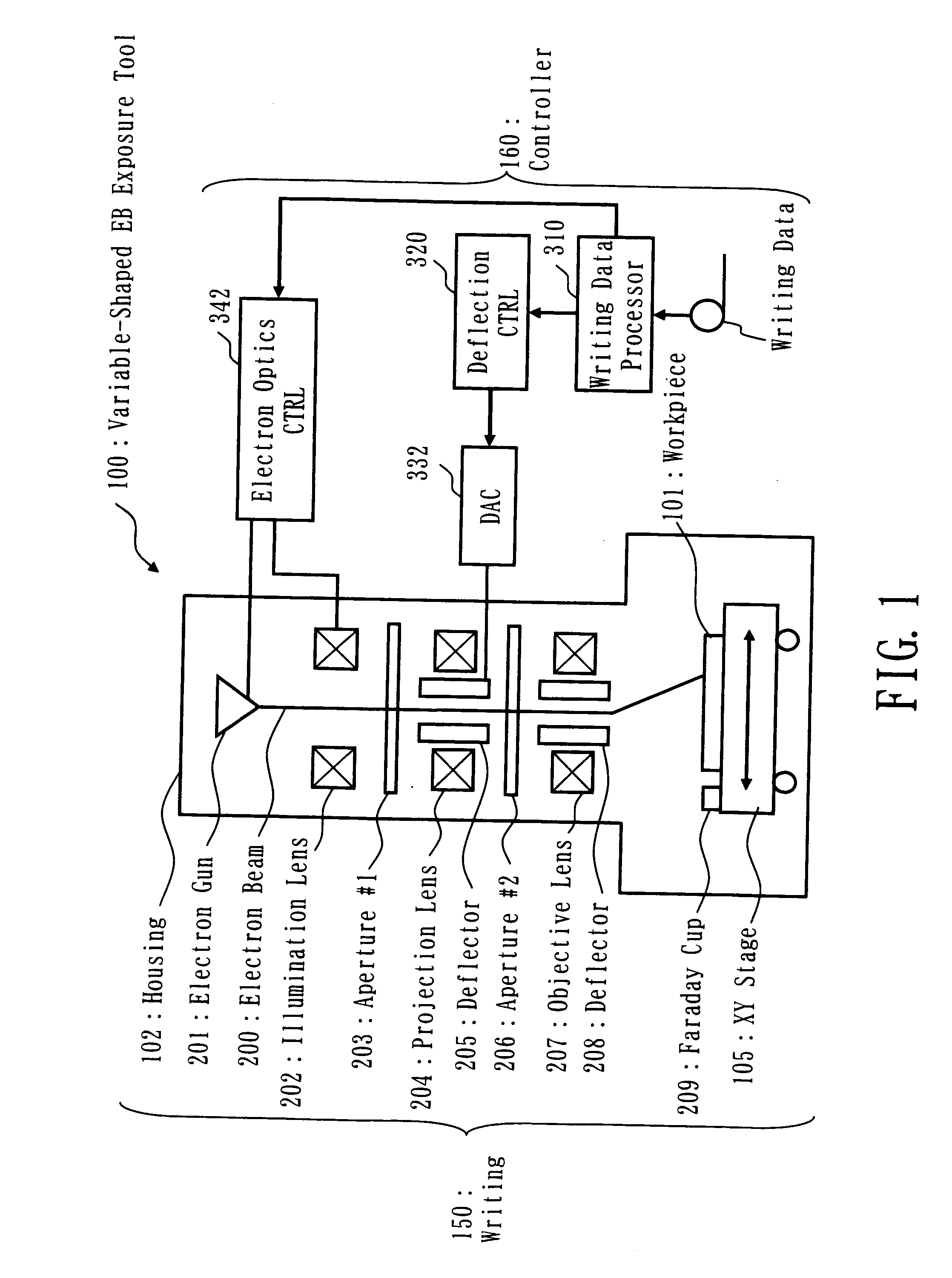
[0040] Referring to FIG. 1, a variable-shaped electron beam (EB) microlithographic pattern writing / exposure apparatus 100 in accordance with a first embodiment of this invention is shown in schematic block diagram form. This EB lithography apparatus is generally made up of a scanning beam pattern writing unit 150 and a system control unit 160 as operatively associated therewith. The pattern writing or “imaging” unit 150 includes a tower-like housing 102 called the electron optical colum, a stage structure 105 that is movable in X and Y directions, an electron gun assembly 201, an illumination lens 202, an upper beam-shaping aperture plate 203 as will be referred to as “first aperture” hereinafter, a projection lens 204, a deflector 205, a lower beam-shaping aperture plate (second aperture) 206, an objective lens 207, a deflector 208, and a Faraday cup 209. The system controller 160 includes a draw data processing circuit 310 that functions as a data selector, a beam deflection contr...
embodiment 2
[0084] While the first embodiment stated above is arranged to perform value setup by selecting in combination the current density J and maximum shot size L which minimize the writing time T, similar results are obtainable by selection of a maximal shot area S in place of the maximum shot size L. A variable-shaped electron beam pattern writing / exposure method and an apparatus for use therewith in accordance with a second embodiment of the invention are arranged to incorporate this principle, although detailed explanations thereof are eliminated herein as these are understandable from the description of the first embodiment while reading it by changing the term “maximum shot size L” to “maximum shot area S.”
[0085] The current density J is given by a beam current value I per unit area. Additionally, as previously stated, the degree of beam defocusing or increasing of beam blur due to space charge effects is variable depending on the beam current value I. Letting the maximum beam curren...
embodiment 3
[0095] While in the above embodiments the current density J is set so that the beam current I flowing in a region of either the squared value of maximum shot size L or the maximum shot area S becomes equal to a specific value which avoids degradation of the beam resolution, every shot area does not always become such expected area when consideration is given for respective shots. In view of this, it is also preferable to vary the current density J on a per-shot basis. One desirable approach is to vary the current density J pursuant to each shot size or each shot area in a way such that the value I of a beam current being shot onto a workpiece 101 is in maximal proximity to a preset beam current value Imax without the risk of beam resolution degradation while letting the former be less than the latter. Varying the current density J in deference to each shot size or area makes it possible to increase the current density of a shot having its area less than either the squared value of t...
PUM
 Abstract
Description
Claims
Application Information