Metal-air battery system with programmed-timing activation

a fuel cell and metal-air technology, applied in the direction of batteries, primary cell maintenance/servicing, cell components, etc., can solve the problems of reducing the useful life of batteries, and inefficient use of anodes

Inactive Publication Date: 2007-02-08
FORD CHEER INT
View PDF21 Cites 23 Cited by
  • Summary
  • Abstract
  • Description
  • Claims
  • Application Information

AI Technical Summary

Problems solved by technology

In addition to the above oxygen-reducing reactions, there is also an undesirable, non-beneficial reaction of aluminum in both types of electrolyte to form hydrogen, as follows:
This effectively reduces the useful battery life and makes inefficient use of the anode material.
(1) Severe “anode passivation” problem: When the battery is run under high load, large amounts of aluminum hydroxide accumulate on the aluminum anode surface blocking the further access of anode by the electrolyte.
All metal anodes used in state-of-the-art metal-air batteries are known to suffer from the anode passivation problem to varying degrees.
(2) Severe self-discharge and current leakage problems: “Self-discharge” is due to a chemical reaction within a battery that does not provide a usable electric current.
These problems also result in a low-utilization anode.
Despite the fact that metals such as Al, Mg, and Li have a much higher energy density than zinc, the three metals (Al, Mg, and Li) suffer from severe corrosion problems during storage.
The presence of oxygen tends to aggravate the corrosion problem.
It is a great pity that high power or energy density metals like Al, Mg and Li have not been extensively used in a primary or secondary cell.
However, just like aluminum-air cells, zinc-air batteries also suffer from the problem of “passivation”, in this case, by the formation of a zinc oxide layer that prevents the remaining anode active material (Zn) from contacting the electrolyte.
The large amount of electrolyte added significantly increased the total weight of the battery system and, thereby, compromising the specific energy density (energy per unit weight).
With excessively small zinc particles, however, zinc was rapidly consumed due to self-discharge and leakage (regardless if the battery is in use or not) and even more serious corrosion problems and, hence, the battery will not last long.
Most of these mechanically rechargeable systems are quite complex in construction.
However, this battery structure is very complicated and its operation could present a reliability problem.
The above-cited batteries proposed by Rao, et al. and by Flanagan have the following drawbacks: These batteries involve the operation of a complicated electrolyte delivery system.
Furthermore, no “air admittance on demand” concept was utilized in these batteries; the cell was exposed to the outside air at all times.
However, this solubility step is often not a slow step particularly when the oxygen or air ingress rate into the cell is high.
This anode bag provides only a moderately effective approach to reducing the self-discharge problem.
This is achieved at the expense of making the cell structure very complicated.
In this manner, the battery is open to the possibility of harsh ambient conditions such as very high or very low ambient relative humidity, prolonged carbon dioxide exposure, etc.
Quite often, this user does not know if the battery in operation is running low in power and should be replaced or recharged immediately.
Further, these prior-art batteries are each composed of an assembly of metal-air cells connected in series (e.g., in Mathews, et al., U.S. Pat. No. 4,177,327) and they do not address the issues of timing at which an individual cell assembly is actuated.
This actively controlled battery has an exceptionally long operating life.

Method used


Image

  • Metal-air battery system with programmed-timing activation
  • Metal-air battery system with programmed-timing activation
  • Metal-air battery system with programmed-timing activation

Examples


example 1

Control Sample

[0087] To further illustrate the battery design concepts inherent in the present invention, let us use a current zinc-air battery (Model EF-M2-33 for use in Motorola StarTAC mobile phone) as an example. The battery is rated at a power capacity of 3300 mAh×3.6 v=11.88 watt-hours. The battery is designed to provide a “talk time” of 6-16 hours or “stand-by” time of 80-350 hours (3.33-14.6 days). With an energy density of 980 watt-hours / Kg for Zn, this capacity requires at least 12.1 grams of Zn (i.e., 11.88 / 980=0.0121 Kg). In actuality, much more Zn was used in this commercially available battery. The total weight of this battery (Zn plus overhead weights) is rated at 79 grams.

[0088] In order to extend the “stand-by” time to 30 days, an approximate Zn anode amount of 25 grams will be required, provided that all 25 grams of Zn is fully utilized. Unfortunately, by simply doubling the amount of unprotected Zn in anode did not double the “stand-by” time, presumably due to t...

example 2

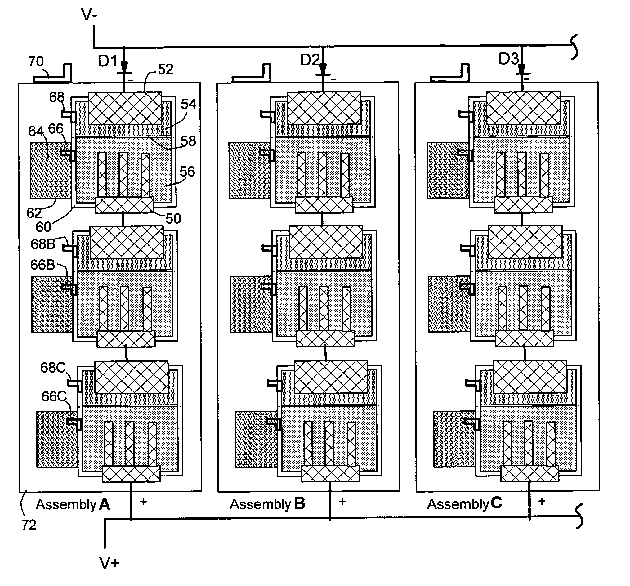
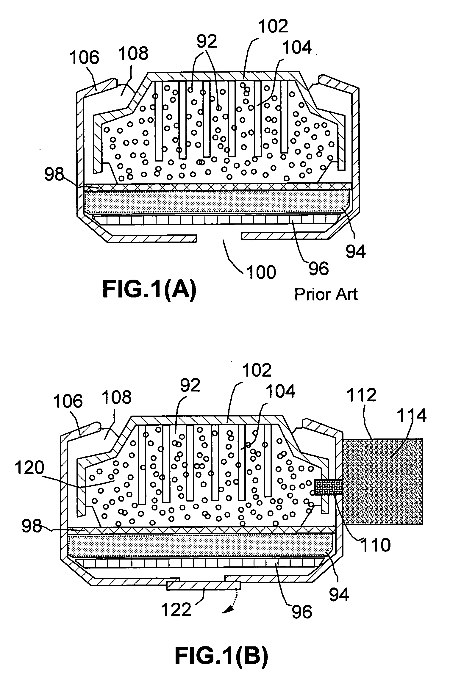
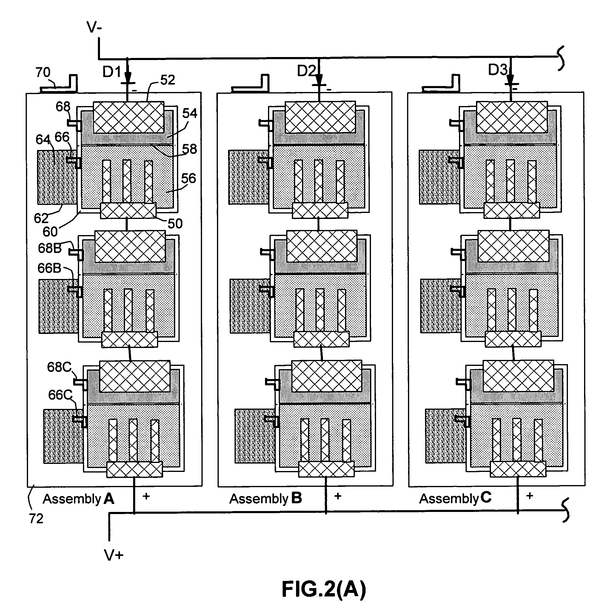
[0089] In accordance with the present invention, a new Zn-air battery was designed in such a way that the first 12 grams of Zn, in a fine powder form (average particle size of 8-20 μm), was packed together and attached to a copper-based current collector. This first 12 grams of Zn in contact with the KOH electrolyte Oust like in a conventional Zn-air cell) was packed in a first cell assembly and provides the first 14 days of stand-by time to a mobile phone. This first 12 grams of Zn in the present invention is referred to as the “initial-stage” anode active material. The next 13 grams of Zn, also in the form of fine particles but initially isolated from KOH solution, was used in the second cell assembly and got activated after slightly less than 14 days (allowing KOH solution to come in contact with the Zn particles). These 13 grams of Zn provided approximately 15.5 days of stand-by time, making the total stand-by time now up to 29.5 days. This was possible due to the fact that, wit...

example 3

[0090] Again, 12 grams of Zn was used as the first-stage anode active material and additional 13 grams of Zn was used as the second-stage anode active material, as in the above Example 2. In the present Example 3, however, the second-stage anode material was initially isolated from KOH solution and air was not admitted into the cell during the first stage. At the end of the first 14 days, KOH was allowed to flow into the anode compartment and air was admitted into the cell. These extra 13 grams of Zn were found to provide up to approximately 16.5 days of operation. The fact that the controlled-timing activation functions to expose an anode active material to the electrolyte liquid and oxygen at the correct timing with the purpose of protecting an anode active material against corrosion, passivation, and self-discharge makes this class of exceptionally long operating life batteries technically feasible and economically viable.


PUM

PropertyMeasurementUnit
period of timeaaaaaaaaaa
output voltageaaaaaaaaaa

Abstract

This invention provides an actively controlled battery with a programmed-timing actuation capability. As a preferred embodiment, the battery comprises a first electrochemical assembly, at least a second electrochemical cell assembly electronically connected in parallel with the first assembly, and control means in control relation to the first assembly and the at least second assembly, wherein at least one of the assemblies comprises a metal-air cell comprising a cathode being isolated from outside air through a controllable air vent and at least one of the assemblies comprising an electrochemical cell comprising an anode active material being initially isolated from an electrolyte fluid through a control valve, with both the air vent and control valve being regulated by the control means to open the air vent and control valve in a programmed-timing fashion. The battery has an exceptionally long operating life and is particularly useful for powering microelectronic or communication devices such as mobile phones, laptop computers, and palm computers.

Description

BACKGROUND OF THE INVENTION [0001] 1. Field of the Invention [0002] The present invention relates to a metal-air battery or fuel cell with a long operating life. In particular, this invention relates to a multiple-cell battery or fuel cell with the constituent metal-air cells being activated in a programmed-timing manner to achieve an extended operating life and better utilization of the capacity of individual cells. [0003] 2. Brief Description of the Prior Art [0004] Metal-air batteries produce electricity by the electrochemical coupling of a reactive metallic anode to an air cathode through a suitable electrolyte in a cell. The air cathode is typically a sheet-like member, having one surface exposed to the atmosphere and another surface exposed to the aqueous electrolyte of the cell. During cell operation oxygen is reduced within the cathode while anode metal is oxidized, providing a usable electric current that flows through an external circuit connected between the anode and the...

Claims


Application Information

Patent Timeline
Patent Type & Authority Applications(United States)
IPC IPC(8): H01M12/06H01M2/12H01M6/50H01M8/04H01M10/42
CPCH01M10/42H01M2200/00H01M12/06H01M10/4257Y02E60/10
Inventor HUANG, WEN C.
Owner FORD CHEER INT
Why Eureka
Try Eureka